IoT Workshop at Universidad de La Laguna (ULL) on 2023-10-23
Prerequisites
- Bring your own laptops.
- Some programming knowledge is an advantage but not a must.
- We just have three experimental kits with ESP32 microcontroller.
Dependent on the number of participants you would have to form groups.
Introduction
Internet-of-things (IoT) technologies are a main subject in the maker community for rapid prototyping. They can be used to set up environmental monitoring systems with wireless data transmission and a large variety of sensors. The same technologies can be used to set up easy to use sensor systems for science education in primary shools and beyond.
The workshop at ULL is ment to give some first insights into the IoT technology capabilities to educators of primary school teachers.
For practical reasons we use the WEMOS D1 R32 board with ESP32 in Arduino UNO form factor. The ESP32 microcontroller provides wireless data transmission by WiFi as well as Bluetooth. We chose the D1 R32 board beacuse it was available at the shop Faro Electronica La Laguna.
 |
| WEMOS D1 R32 (ESP32) microcontroller board. Source: Design Tech Auckland |
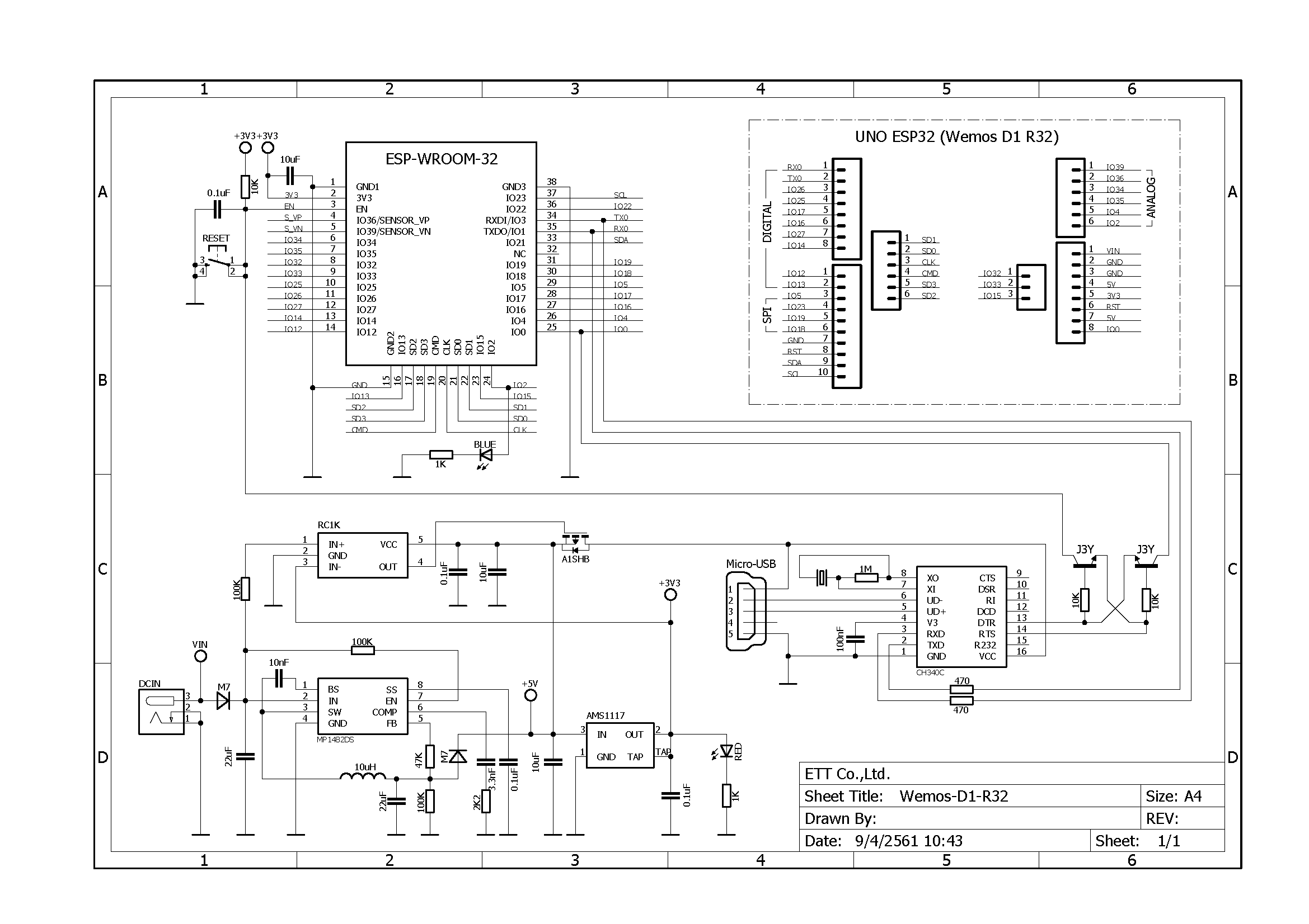 |
| WEMOS D1 R32 (ESP32) SCHEMATIC. Click to enlarge. |
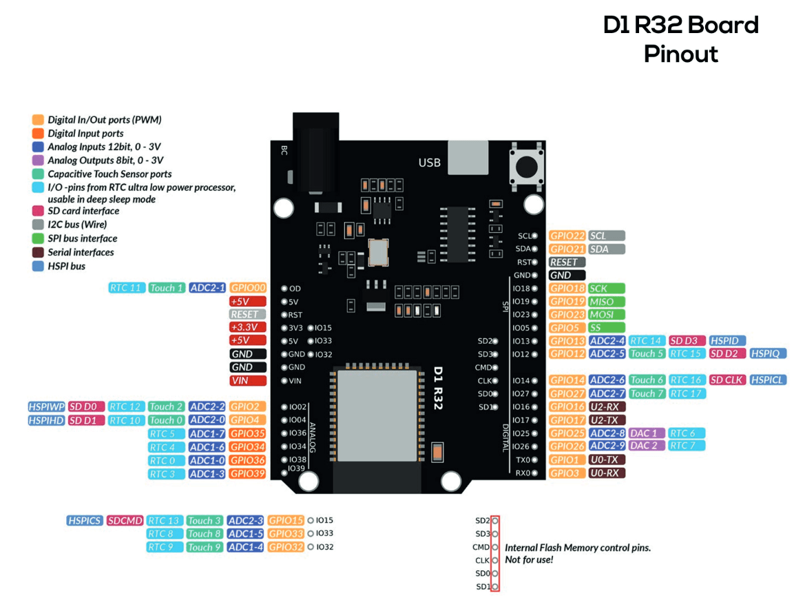 |
| WEMOS D1 R32 (ESP32) PINOUT. Click to enlarge. |
Installation
1. Install the latest Arduino IDE from arduino.cc on your computer
Download and follow the instructions from here: https://www.arduino.cc/en/software
We encountered some  problems with the Linux installation
2. Install the latest ESP32 package to extend the Arduino IDE for ESP32
Follow the instructions here:
https://docs.espressif.com/projects/arduino-esp32/en/latest/installing.html
Use the stable(!) release of the ESP32 board repository list to populate the Arduino IDE board manager:
https://espressif.github.io/arduino-esp32/package_esp32_index.json
3. Install the USB-to-Serial Driver for the chip CH341
The installation of the Chinese USB chip driver is a bit scary but safe. Download the zip archive CH341SER.ZIP from here:
https://www.wch-ic.com/downloads/CH341SER_ZIP.html
and follow the instructions.
4. Choose the WEMOS D1 R32 board
Plug in the USB cable of the board into your computer.
Click on the “select board” drop down edit box. On the bottom of the dropdown list click on “select other board and port”.
On the left window pane (left section) search for WEMOS D1 R32 and select this as your board.
On the right window pane (right section) you should see a list of ports one of which being annotated as USB. Select that. To double check you can unplug and replug the board and observe how the port list changes.
5. Parametrize the Arduino IDE
Increase verbosity, make the system talkative!
Go to File→Preferences and check the “Show verbose output during” →Compile and →Upload box
Programming
On your computer create your own dedicated Arduino working directory,
on e.g. Windows %userprofile%/Documents/Arduino/myProjects/
Let's go!
1. Blink
This is the “Hello world!” program of Arduino. It lets the built-in LED blink. Most of the common Arduino boards have a general purpose LED on board the user can program. This is a good example to start with to understand the tool chain of programming → compiling → uploading as well as the essential program structure of any Arduino program.
Choose from the menu File→Examples→01.Basics→Blick. This opens a new editor window. Save a copy of this file by choosing File→Save as … . Save it in your newly created Arduino working directory onder the name myBlink.
In the Arduino IDE choose the right board and port.
Compile and upload the code by pressing the right arrow “→” in the horizontal green Arduino IDE tool bar (just below the menu items).
Observe the output on the black terminal window in the bottom window pane.
When successful the red LED on the board should blink.
The essentials of the Blink code:
- myBlink.ino
// the setup function runs once when you press reset or power the board
void setup() {
  // initialize digital pin LED_BUILTIN as an output.
  pinMode(LED_BUILTIN, OUTPUT);
}

// the loop function runs over and over again forever
void loop() {
  digitalWrite(LED_BUILTIN, HIGH);  // turn the LED on (HIGH is the voltage level)
  delay(1000);                      // wait for a second
  digitalWrite(LED_BUILTIN, LOW);   // turn the LED off by making the voltage LOW
  delay(1000);                      // wait for a second
}
2. AnalogInOutSerial
Choose from the menu File→Examples→01.Basics→AnalogOutInSerial. This opens a new editor window. Save a copy of this file by choosing File→Save as … . Save it in your newly created Arduino working directory under the name myAnalogOutInSerial.
/*
  Rolf Becker's remarks:
  CAREFUL! Ugly? On the "WEMOS D1 R32 board" the following pin definitions are used: A0 = Pin 2 = LED_BUILTIN
  The ADC has 12 bits resolution (0 .. 4095) and not 10 bits (0 .. 1023)
  Go for 115200 baud instead of 9600
  Delay 100 ms instead of 2 ms.
*/

// These constants won't change. They're used to give names to the pins used:

//old: const int analogInPin = A0; // Analog input pin that the potentiometer is attached to
const int analogInPin = A5;  // Analog input pin that the potentiometer is attached to

//old: const int analogOutPin = 9;  // Analog output pin that the LED is attached to
const int analogOutPin = 2;  // Analog output pin that the LED is attached to

int sensorValue = 0;  // value read from the pot
int outputValue = 0;  // value output to the PWM (analog out)

void setup() {
// initialize serial communications at 9600 bps:
//old:  Serial.begin(9600);
  Serial.begin(115200);
}

void loop() {
  // read the analog in value:
  sensorValue = analogRead(analogInPin);

  // map it to the range of the analog out:
  //old: outputValue = map(sensorValue, 0, 1023, 0, 255);
  outputValue = map(sensorValue, 0, 4095, 0, 255);

  // change the analog out value:
  analogWrite(analogOutPin, outputValue);

  // print the results to the Serial Monitor:
  Serial.print("sensor = ");
  Serial.print(sensorValue);
  Serial.print("\t output = ");
  Serial.println(outputValue);

  // wait 2 milliseconds before the next loop for the analog-to-digital
  // converter to settle after the last reading:
  //old: delay(2); // 500 Hz
  delay(100); // 10 Hz
}
3. Multi-Tasking
Example from https://solectroshop.com/es/content/125-tutorial-para-la-placa-wemos-d1-esp32-r32-wroom-32-wifi-y-bluetooth
- esp32-tasks.ino
void setup() {
 Serial.begin(112500);
 pinMode(2, OUTPUT);
 vTaskDelay(1000 / portTICK_PERIOD_MS);
 xTaskCreate(task1,"task1", 2048, NULL,1,NULL);
 xTaskCreate(task2,"task2", 2048, NULL,1,NULL);
}
void loop() {
 vTaskDelay(1000 / portTICK_PERIOD_MS);
}
void task1( void * parameter )
{
  while(1) {
   Serial.println("Hello World!");
   vTaskDelay(1000 / portTICK_PERIOD_MS);
  }
}
void task2( void * parameter)
{
  while(1) {
     digitalWrite(2, HIGH);
     vTaskDelay(500 / portTICK_PERIOD_MS);
     digitalWrite(2, LOW);
     vTaskDelay(500 / portTICK_PERIOD_MS);
  }
}
4. WiFi Scanner
Select: File → Examples → WiFi → WiFiScan
5. DHT11 with ESP32
Internet of Things: MQTT Protocol
Workshop at UNICAES 2023, El Salvador (Harley Lara)
Sources
Wemos R32 with Arduino - Startup Guide! (hackster.io)
Datesheets
Tutorial: Internet de las cosas!
Tutorial: DS18B20
Backgroup Information
ESP32 Board Variant WEMOS D1 R32 (aka d1_uno32)
Folder with the board specific description file pins_arduino.h defining pin names and other parameters for the previously installed esp32 package version 2.0.14:
- Folder on Windows:
%LOCALAPPDATA%\Arduino15\packages\esp32\hardware\esp32\2.0.14\variants\d1_uno32\ - Folder on Linux: to be done
- Folder on Mac: to be done
The content of the pins_arduino.h for WEMOS D1 R32:
- wemos_d1_r32_arduino.h
#ifndef Pins_Arduino_h
#define Pins_Arduino_h

// Board Pinmap: https://www.botnroll.com/en/esp/3639-wemos-d1-r32-w-esp32-uno-r3-pinout.html

#include <stdint.h>


#define EXTERNAL_NUM_INTERRUPTS 16
#define NUM_DIGITAL_PINS        40
#define NUM_ANALOG_INPUTS       16

#define analogInputToDigitalPin(p)  (((p)<20)?(analogChannelToDigitalPin(p)):-1)
#define digitalPinToInterrupt(p)    (((p)<40)?(p):-1)
#define digitalPinHasPWM(p)         (p < 34)

static const uint8_t TX = 1;
static const uint8_t RX = 3;

static const uint8_t SDA = 21;
static const uint8_t SCL = 22;

static const uint8_t SS    = 5;
static const uint8_t MOSI  = 23;
static const uint8_t MISO  = 19;
static const uint8_t SCK   = 18;

static const uint8_t A0 = 2;
static const uint8_t A1 = 4;
static const uint8_t A2 = 35;
static const uint8_t A3 = 34;
static const uint8_t A4 = 36;
static const uint8_t A5 = 39;

static const uint8_t LED_BUILTIN = 2;
#define BUILTIN_LED  LED_BUILTIN // backward compatibility
#define LED_BUILTIN LED_BUILTIN

#define PIN_WIRE_SDA SDA // backward compatibility
#define PIN_WIRE_SCL SCL // backward compatibility

static const uint8_t D0   = 3;
static const uint8_t D1   = 1;
static const uint8_t D2   = 26;
static const uint8_t D3   = 25;
static const uint8_t D4   = 17;
static const uint8_t D5   = 16;
static const uint8_t D6   = 27;
static const uint8_t D7   = 14;
static const uint8_t D8   = 12;
static const uint8_t D9   = 13;
static const uint8_t D10  = 5;
static const uint8_t D11  = 23;
static const uint8_t D12  = 19;
static const uint8_t D13  = 18;

#define PIN_SPI_SS   SS   // backward compatibility
#define PIN_SPI_MOSI MOSI // backward compatibility
#define PIN_SPI_MISO MISO // backward compatibility
#define PIN_SPI_SCK  SCK  // backward compatibility

#define PIN_A0 A0 // backward compatibility

#endif /* Pins_Arduino_h */