I used this components:
- Adafruit Feather Huzzah ESP8266
- Rotary Encoder with Button
- 128x64 OLED I2C OLED Display
- 2000mAh 1C LiPo Battery
- Micro-USB Breakout (just for charging in the case (I was to lazy to design the case so the Feather sits perfectly to charge it directly))
- Some M3 (2x longer ones for the Rotary Encoder + 2x 8mm for the case) and M2 (2x 10mm for the display) bolts and nuts
- Some hook up wire (I just assembled nearly everything outside the case and jammed it all in the little box)
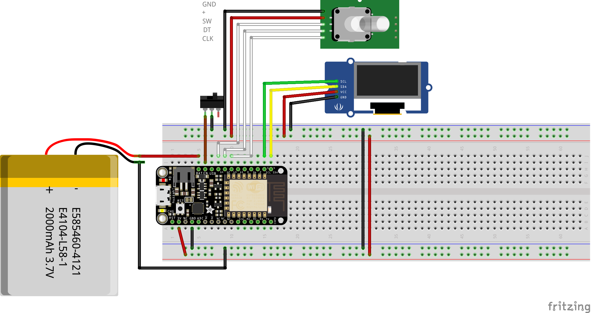
Here you can see the schematic on a breadboard. Not hard. If it fits you can plug in the LiPo directly into the feather without the need of the BAT-Pin.
The firmware for the feather can be found in the Controller-Folder. It can be opened with the Arduino IDE. It uses the following non-standard libraries:
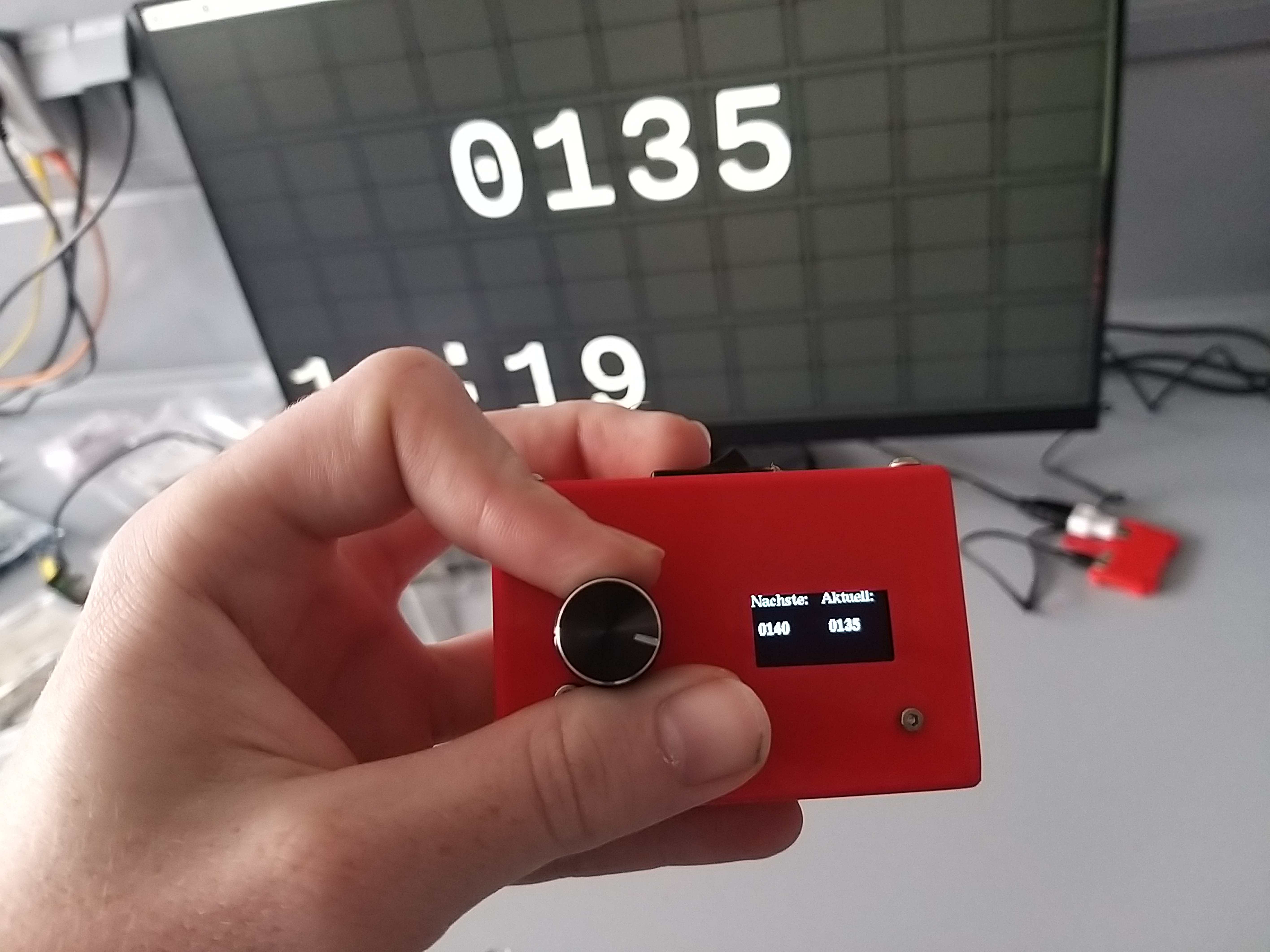
Right now the interface is in german, but there are only two words to translate that should be doable (Nächste -> Next | Aktuell -> Current).
The ESP8266 will first try to connect to the WiFi of the Raspberry. The SSID and Password can be changed in code. While connecting a blinking dot is displayed on the display. After connecting it will get the currently displayed number from the Node.js server. You can then set the next number with the rotary encoder either by rotating until you get to the desired number or incrementing one by a short press. To send the new number you have to long press the button for atleast half a second. If you let go of the button the new number will be send to the server. While doing so the controller display reacts accordingly. The minimum number to be displayed is 0 and the max number is 9999.

