This is an old revision of the document!
ESP32 Deep Sleep Mode
In this project the ESP32 is idle for more than 95% of the time because it is supposed to take measurements only once an hour, transmit the data and wait again. However, the ESP32 has the possibility to be run in different power modes. Besides the active mode where all peripherals are powered, there are also the modem-sleep mode, light-sleep mode, deep-sleep mode, hibernation mode and power-off mode.
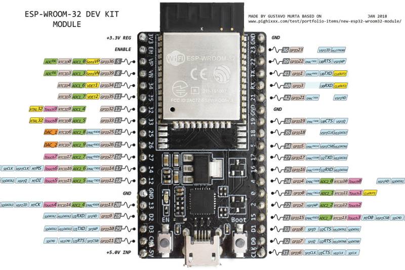
As explained in the DS3231 page, the ESP32 can be put to sleep to save a lot of energy from the battery and only wake up once an hour by an interrupt signal from the DS3231 RTC module. For the ESP32 to wake up from an external interrupt, the real time clock (RTC) peripherals (RTC timer + RTC memory) must remain powered on. The power mode with the lowest energy consumption and RTC peripherals still powered on is the deep sleep mode with only RTC timer and RTC memory powered. In this mode, the module draws only 10 $\mu A$ of current, which is a several thousand times less than in the active mode (see the ESP32 datasheet pp 23 -24). However, like this it is only possible to use the RTC_GPIO pins (figure 1), not the other GPIOs to read the interrupt signal.
 |
|---|
| Figure 1 ESP32 DevKit Pinout (Source: ESP32 DevKit 38 Pins) |
Setup of the DS3231 with the ESP32
As the DS3231 is an open drain device, the SQW pin connected to one of the RTC_GPIO pins needs to be pulled to high voltage using a pullup resistor. In the case of the Arduino UNO sketch, the Arduino's internal pullup resistor was used. The ESP32 also has internal pullup resistors, but their value strongly fluctuates from module to module and pin to pin and generally lies between 30 - 80 kΩ. Furthermore, it is somewhat complicated to control the pins during deep sleep mode to activate the pullups. Therefore, a 100kΩ external pullup resistor was used to connect the interrupt pin to 3.3V which also results in a lower current being drawn when the interrupt is triggered.
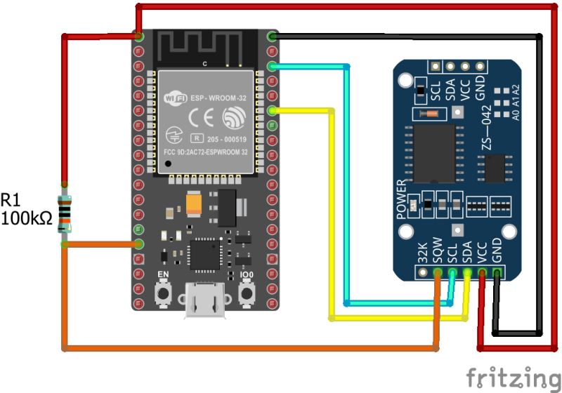
The DS3231 was connected the following way:
- VCC to 3.3 V
- GND to GND
- SDA to GPIO 21
- SCL to GPIO 22
- SQW to GPIO 13 (RTC_GPIO14) (and 3.3V through the pullup resistor).
The connections can also be seen in the diagram in figure 2.

