This is an old revision of the document!
Table of Contents
Trough Automation PCB - Documentation
Here you can find all the necessary information to work with the Trough Automation PCB in your own project.
General Concept and internal workings
The board was developed as an easy tool to switch high loads remotely and automatically based on sensor readings done by the same board or even other sensors in the surroundings. It can connect to Wifi and can also be reconfigured without programming the whole board, thanks to Tasmota.
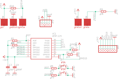
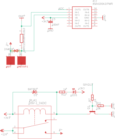
The board's main chip is an ESP8266, more specifically the ESP-12F. It can control a relay and has a current meter connected to the ADC which meters the current attached to the high voltage output. Furthermore, all GPIOs are available for attaching sensors. GPIO 14 is routed out specifically for OneWire Devices.
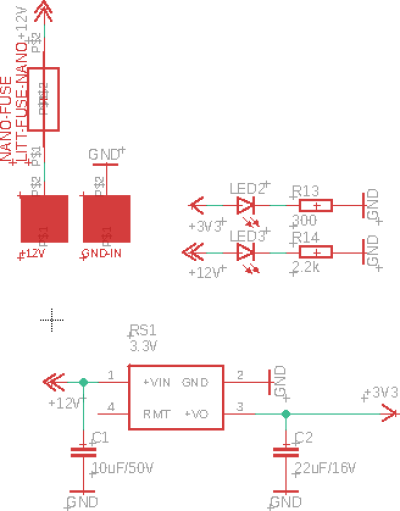
Power Management
MCU
High Voltage Switching Side
How to program
Other possibilities
Future improvements
- C1 should have a bigger footprint
- Add a voltage divider in front of the ADC
- There should™ be no copper under the PCB Antenna of the ESP8266
- The 4-channel current meter is suboptimal, to say the least (thanks chip-shortage)


