This is an old revision of the document!
Table of Contents
Trough Automation PCB - Documentation
Here you can find all the necessary information to work with the Trough Automation PCB in your own project.
General Concept and internal workings
The board was developed as an easy tool to switch high loads remotely and automatically based on sensor readings done by the same board or even other sensors in the surroundings. It can connect to Wifi and can also be reconfigured without programming the whole board, thanks to Tasmota.
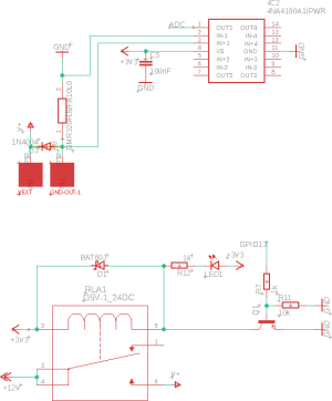
The board's main chip is an ESP8266, more specifically the ESP-12F. It can control a relay and has a current meter connected to the ADC which meters the current attached to the high voltage output. Furthermore, all GPIOs are available for attaching sensors. GPIO 14 is routed out specifically for OneWire Devices.
Power Management
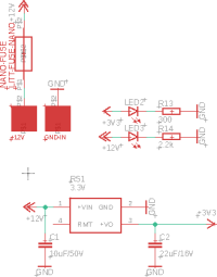
 The power management side is held pretty simple. The main work is done by a daughter board by RS Pro. It has an input voltage of 4.75V to 36V and can deliver a maximum of 500mA. It puts out a constant voltage of 3.3V, used by all the controlling electronics. The remote pin of the module is not used or routed out at the moment. This could be used as an on and off switch. In front of the regulator sits a nano fuse. This can differ from board to board. (So have a close look at that!) There are status LEDs for both 12V and 3.3V. When using another voltage than 12V, R14 may have to be adjusted, so the LED does not blow out. Both should light up clearly when using the board with 12V. When only 3.3V is connected to the programming header, the 3.3V LED will light up normally but the 12V LED will not be fully lit up. Never connect an FTDI-Breakout to the 3.3V-Pin when a high voltage is connected to the board!
MCU
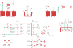
 The ESP8266/ESP-12F is implemented as described in the datasheet: Datasheet ESP12-F (5. Application circuit). Furthermore, some extra parts got added. To program the board it has to be set into the programming mode. Therefore two extra buttons are needed. These are hooked up to the reset pin and GPIO0. Two GPIOs are routed to specific solder pads needed in the application as a trough-automation. GPIO14 is pulled high so OneWire sensors like the DS18B20 can be attached directly to the solder pads. There are also solder pads for a button or a switch of some sort connected to GPIO12. It is normally pulled low. So a button press could be recognized as a rising edge. All other unused GPIOs (except GPIO2) are routed out to a little “development area”. In this area, other sensors or daughter boards could be attached. Some examples can be found below in “Other possibilities”.
High Voltage Switching Side
How to program
Other possibilities
Future improvements
- C1 should have a bigger footprint
- Add a voltage divider in front of the ADC
- There should™ be no copper under the PCB Antenna of the ESP8266
- The 4-channel current meter is suboptimal, to say the least (thanks chip-shortage)
- The dot for the RS PRO Regulator is placed wrong

