Table of Contents
ESP32 Deep Sleep Mode
1. About ESP32 Deep Sleep
In this project the ESP32 is idle for more than 95% of the time because it is supposed to take measurements only once an hour, transmit the data and wait again. However, the ESP32 has the possibility to be run in different power modes. Besides the active mode where all peripherals are powered, there are also the modem-sleep mode, light-sleep mode, deep-sleep mode, hibernation mode and power-off mode.
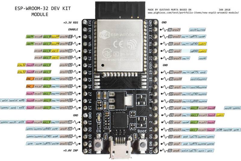
As explained in the DS3231 page, the ESP32 can be put to sleep to save a lot of energy from the battery and only wake up once an hour by an interrupt signal from the DS3231 RTC module. For the ESP32 to wake up from an external interrupt, the real time clock (RTC) peripherals (RTC timer + RTC memory) must remain powered on. The power mode with the lowest energy consumption and RTC peripherals still powered on is the deep sleep mode with only RTC timer and RTC memory powered. In this mode, the module draws only 10 $\mu A$ of current, which is a several thousand times less than in the active mode (see the ESP32 datasheet pp 23 -24). However, like this it is only possible to use the RTC_GPIO pins (figure 1), not the other GPIOs to read the interrupt signal.
 |
|---|
| Figure 1 ESP32 DevKit Pinout (Source: ESP32 DevKit 38 Pins) |
2. Setup of the DS3231 with the ESP32
As the DS3231 is an open drain device, the SQW pin connected to one of the RTC_GPIO pins needs to be pulled to high voltage using a pullup resistor. In the case of the Arduino UNO sketch, the Arduino's internal pullup resistor was used. The ESP32 also has internal pullup resistors, but their value strongly fluctuates from module to module and pin to pin and generally lies between 30 - 80 kΩ. Furthermore, it is somewhat complicated to control the pins during deep sleep mode to activate the pullups. Therefore, a 100kΩ external pullup resistor was used to connect the interrupt pin to 3.3V which also results in a lower current being drawn when the interrupt is triggered.
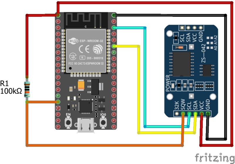
The DS3231 was connected the following way:
- VCC to 3.3 V
- GND to GND
- SDA to GPIO 21
- SCL to GPIO 22
- SQW to GPIO 13 (RTC_GPIO14) (and 3.3V through the pullup resistor).
The connections can also be seen in the diagram in figure 2.
3. Programming
After setting up the module with the ESP32, the programming for the deep sleep is very simple. For the following test, the DS3231 was programmed to trigger an interrupt once a minute, i.e. the setting was changed to ALARM_SECONDS_MATCH. How to do that is explained in the DS3231 page.
3.1 Code
- ESP32_DS3231_Deep_Sleep_test.ino
//ESP32 DS3231 Deep Sleep Test

#include <Wire.h>
#define DS3231RTC_I2C_ADDRESS 0x68
#define I2C_SDA 21                                  //1
#define I2C_SCL 22

void clearAlarm1(){                                 //2
  Wire.beginTransmission(DS3231RTC_I2C_ADDRESS);
  Wire.write(0x0F);
  Wire.write(B00000000);
  Wire.endTransmission();
}

void setup() {
  Wire.begin(I2C_SDA, I2C_SCL);                     //3
  clearAlarm1();                                    //4
  Serial.begin(115200);                             //5
  delay(1000);
  Serial.println("ESP32 woke up from deep sleep.");
  for(int i=3;i>=0;i--){
    Serial.print("Going back to sleep in ");
    Serial.println(i);
    delay(1000);
  }
  esp_sleep_enable_ext0_wakeup(GPIO_NUM_13,0);      //6
  esp_deep_sleep_start();                           //7
  Serial.println("This will never be printed.");    //8
}

void loop() {
  //This is not going to be called.
}
3.2 The Code Explained
- After including the Wire.h library for I2C communication and defining the DS3231 I2C address as 0x68, the I2C pins of the ESP32 need to be defined. By default SCL is GPIO 22 and SDA is GPIO 21, but it is possible to use almost all pins for I2C communication if done correctly. Here just the default pins are used.
- The function clearAlarm1() is the only one, that must be copied into the new sketch.
- When using the Wire.begin() method to start the I2C bus, the I2C pins previously defined need to be given as argument.
- After waking up, the alarm flag 1 of the DS3231's status register needs to be reset, otherwise the interrupt is fired continuously and the ESP32 would immediately wake up again after going into sleep mode. Therefore, clearAlarm1() is used to reset the alarm in the beginning.
- The serial connection is started to test whether the sketch is working. After waking up, the ESP32 prints some data to the monitor. Then a counter is counting down from 3 to 0 and the ESP32 goes back into deep sleep.
- The function esp_sleep_enable_ext0_wakeup() defines the method for waking the ESP32 up from deep sleep. The ext0 means that the the wake up source is external and can only be triggered by a single pin. The number of the pin is given in the argument as GPIO_NUM_X where X represents the GPIO number of that pin. The second argument (level) defines which state the pin needs to be in to wake the ESP32 up. A 1 means that it will wake up, when the voltage is 3.3V. A 0 means it wakes up when it is 0V. As the DS3231 pulls the pin to GND when the alarm is activated, the level needs to be 0.
- The function esp_deep_sleep_start() changes the power mode of the ESP32 to deep sleep.
- When the deep sleep is activated, the rest of the program code is just not executed. After resetting, the ESP32 starts again with the setup(). Therefore, this line should never be printed to the serial monitor; otherwise there is an error. The program also never reaches the main loop().
3.3 Results
Apart from the timestamps on the left, the result in the serial monitor should look like this. In the data that the ESP32 prints by itself, it can be seen that the reset occured due to waking up from deep sleep (1). Furthermore, the last serial print command was not executed because deep sleep was activated before that could happen.
When comparing the time stamps (1, 3 and 4) it becomes visible that the wake up from deep sleep occurred always 1 minute after the last wake up. However, the milliseconds are always varying a little bit. This might be due to the temperature compensation of the DS3231 through which the capacitance and therefore the frequency of the oscillator are changed. So, there might be very small inaccuracies, but they are constantly compensated for by the module, such that the total drift stays very low.
18:50:42.643 -> ets Jun  8 2016 00:22:57
18:50:42.643 ->
18:50:42.643 -> rst:0x5 (DEEPSLEEP_RESET),boot:0x13 (SPI_FAST_FLASH_BOOT) //1
18:50:42.643 -> configsip: 0, SPIWP:0xee
18:50:42.643 -> clk_drv:0x00,q_drv:0x00,d_drv:0x00,cs0_drv:0x00,hd_drv:0x00,wp_drv:0x00
18:50:42.643 -> mode:DIO, clock div:1
18:50:42.643 -> load:0x3fff0018,len:4
18:50:42.643 -> load:0x3fff001c,len:1216
18:50:42.643 -> ho 0 tail 12 room 4
18:50:42.643 -> load:0x40078000,len:10864
18:50:42.643 -> load:0x40080400,len:6432
18:50:42.643 -> entry 0x400806b8
18:50:43.793 -> ESP32 woke up from deep sleep.
18:50:43.793 -> Going back to sleep in 3
18:50:44.783 -> Going back to sleep in 2
18:50:45.743 -> Going back to sleep in 1
18:50:46.743 -> Going back to sleep in 0                                  //2
18:51:42.633 -> ets Jun  8 2016 00:22:57                                  //3
18:51:42.633 ->
18:51:42.633 -> rst:0x5 (DEEPSLEEP_RESET),boot:0x13 (SPI_FAST_FLASH_BOOT)
18:51:42.633 -> configsip: 0, SPIWP:0xee
18:51:42.633 -> clk_drv:0x00,q_drv:0x00,d_drv:0x00,cs0_drv:0x00,hd_drv:0x00,wp_drv:0x00
18:51:42.633 -> mode:DIO, clock div:1
18:51:42.633 -> load:0x3fff0018,len:4
18:51:42.633 -> load:0x3fff001c,len:1216
18:51:42.633 -> ho 0 tail 12 room 4
18:51:42.633 -> load:0x40078000,len:10864
18:51:42.633 -> load:0x40080400,len:6432
18:51:42.633 -> entry 0x400806b8
18:51:43.782 -> ESP32 woke up from deep sleep.
18:51:43.782 -> Going back to sleep in 3
18:51:44.763 -> Going back to sleep in 2
18:51:45.753 -> Going back to sleep in 1
18:51:46.763 -> Going back to sleep in 0
18:52:42.653 -> ets Jun  8 2016 00:22:57                                  //4
18:52:42.653 ->
18:52:42.653 -> rst:0x5 (DEEPSLEEP_RESET),boot:0x13 (SPI_FAST_FLASH_BOOT)
18:52:42.653 -> configsip: 0, SPIWP:0xee
18:52:42.653 -> clk_drv:0x00,q_drv:0x00,d_drv:0x00,cs0_drv:0x00,hd_drv:0x00,wp_drv:0x00
18:52:42.653 -> mode:DIO, clock div:1
18:52:42.653 -> load:0x3fff0018,len:4
18:52:42.653 -> load:0x3fff001c,len:1216
18:52:42.653 -> ho 0 tail 12 room 4
18:52:42.653 -> load:0x40078000,len:10864
18:52:42.653 -> load:0x40080400,len:6432
18:52:42.653 -> entry 0x400806b8
18:52:43.753 -> ESP32 woke up from deep sleep.
18:52:43.753 -> Going back to sleep in 3
18:52:44.753 -> Going back to sleep in 2
18:52:45.793 -> Going back to sleep in 1
18:52:46.783 -> Going back to sleep in 0

