Table of Contents
Plant farming automation system
Applied Measurement and Control, Professor Becker, SS2021
Group B: Jonas Geßmann, 25192; Binta Mariam Khan 27638
Table of content
1.Introduction
2.Materials and Method
3.Results
4.Discussion
5.Video summary
6.References
1. Introduction
Plant growth is influenced by many environmental factors like water, light and nutrient availability. To enhance the growth rate of a plant, the specific conditions must be met. The goal of precision farming is to optimize the growth rate while making it as efficient as possible based on measured factors. This can also reduce the impact on the environment such that fertilizer usage can be reduced and applied only where it is necessary.
Automating the processes can further reduce manual work done by human labour. Although some environmental factors can be easily measured accurately, some still require manual input to ensure accurate data, such as plant growth height or health status of the plant. This data could be manually be input into the automation to be respected in decisions made by the automation.
Our goal in this project is to build a system that can automate tasks for farming in a controlled area. The system can be used at home for monitoring and watering flowers indoor or in the garden but can be expanded to be used for farming indoor or in a urban environment.
The software used is available as free open source license and has a big community for support and active development. It is used as server infrastructure collecting data from sensors, visualizes the data and based on the collected values it decides to control appliances.
The sensor used in this project is a soil humidity sensor. The controlled appliance in this case is a relay switch powering a water pump that can pump water from a reservoir to the plant’s soil.
In the following the used hardware is presented and tested with the widely distributed Arduino IDE. Further the sensors are calibrated and the basic system is set up. Afterwards the server infrastructure and connections are established and tested.
The system built in this project can easily be expanded to further functions like specialized lighting and fertilizing or more sensors and appliances can take over tasks that would need manual interaction in the current state.
2. Materials and Method
2.1 Hardware
Physical components used for the project:
- ESP32 Microcontroller
- Battery
- Soil Moisture Sensor
- Relay Module
- Water Pump
2.1.1 ESP32 Microcontroller
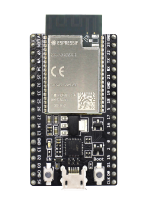
Figure: ESP32-DevKitC_V4 with ESP32-WROVER-B, https://www.espressif.com/sites/default/files/dev-board/ESP32-DevKitC%28ESP32-WROVER-E%29_0.png
Specifications:
Espressif ESP32-DevKitC_V4 with ESP32-WROVER-B module: http://espressif.com/en/products/hardware/esp32-devkitc/overview
Datasheet: https://www.espressif.com/sites/default/files/documentation/esp32-wrover-b_datasheet_en.pdf
ESP32-D0WD chip with 4MB Flash and 8MB PSRAM storage
The processor has 2 CPU cores that can be clocked with a low frequency of 80 MHz up to a high and powerful frequency of 240 MHz, but also has a low-powered co-processor for low-performance tasks like monitoring inputs.
The available peripherals are “capacitive touch sensors, Hall sensors, SD
card interface, Ethernet, high-speed SPI, UART, I²S, I²C, ADC and DAC
The module has Bluetooth v4.2 built in with Bluetooth-Low-Energy specification which enables low power comunication.
For greater distance and higher bandwidth communication the module comes with 2.4 GHz Wifi 802.11 b/g/n with an output power 20 dBm at the antenna and a maximum data rate of 150 Mbps.
OS/Development environment: FreeRTOS / Espressif-IDF, Arduino IDE, Micropython/Circuitpython
Why was this module chosen?
The ESP32 is a powerful microcontroller with many inputs supporting a wide variety of protocols and standards.
It can be easily programmed for testing but can also be used with different specialized frameworks and operating systems.
The main advantage of the ESP32 module we chose, is the connectivity with a fast wifi that enables us to use existing wireless networks that have standards for mesh network communication. Through this we can connect our IoT device to a server where the data can be collected.
2.1.2 Soil Moisture Sensor
This sensor is useful to measure or approximate the water content in the soil where the plant is supposed to have enough but not too much water available.
Based on that data decisions can be made to create optimal growth conditions.
There are different mechanisms to measure:

Figure: Resistive soil moisture sensor, https://hackster.imgix.net/uploads/attachments/810967/hygrometer3-1_Z123DR5BSY.png
Resistive measurement induces a DC current and measures electrical conductivity between two metal plates (electrodes).
Soil resistance increases with drought, as less water can conduct the current.
A comparator activates a digital output when an adjustable threshold is exceeded.
This type of sensor is known to have issues with corrosion in long-term use, as the voltage
together with the water quickly corrodes the metal of the sensor.
It also has shown to lack accuracy of measurements.
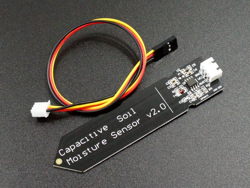
Figure: Capacitive soil moisture sensor, https://protosupplies.com/wp-content/uploads/2020/10/Capacitive-Soil-Moisture-Sensor-Module.jpg
A capacitive soil moisture sensor is considered to be more stable and reliable. It measures the capacity
of the water in the soil between two plates.
This sensor consists of a sealed circuit board and thus is not exposed to water. So the water should not have an impact on the lifetime of the sensor, as long as the other electronic components on the PCB are also sealed or not exposed to water and humidity.
This sensor outputs an analog signal between 0 and 255.
2.1.3 Relay Module

Figure: Relay module, https://www.stephenwenceslao.com/sites/default/files/1-relay-module4.jpg
A relay can safely close a circuit when activated by an external DC current. Thus this electrical switch can be activated by a controlled electrical signal.
There are different configurations and mechanisms that for example are normally open or normally closed relays that both change their state when they are activated, but have a different passive state.
The relay module has additional passive components.
The main electrical input must supply sufficient voltage and current for the appliance that is supposed to be switches. It is also important to regard the peak power needs for example the starting current of a motor.
This means a motor should not be powered off a the power pins of an ESP32 directly as it cannot supply enough current and it might result in a damaged chip if done so.
This is why an external power source is needed for powering the pump but not for activating the relay.
2.1.4 Water Pump

Figure: Submersible water pump, https://cf3.s3.souqcdn.com/item/2018/09/25/38/88/28/88/item_XL_38882888_151555394.jpg
The water pump is supposed to transport water from the storage tank through tubes into the soil. The pump works with an electrical motor that spins a mechanical rotational part, the rotor, which pushes water in an enclosure from an inlet to an outlet and thus creates a flow of the water.
The amount of water transported can be approximately regulated by activating the pump motor for a specified time. The on-time to amount of water pumped relation has to be researched as well as the linearity of these factors.
2.1.6 Hardware Setup

Figure: Fritzing schematic drawing of hardware setup
2.2 Software
2.2.1 Arduino Code
#include <Adafruit_Sensor.h>
#include <WiFi.h> #include <WiFiClient.h>

int sensor_pin = 27;
int output_value ;
const int relay_pin = 15; //digital pin where the relay is plugged in
const char* ssid = “FRITZ!Box 7530 LV”;
const char* password = “08547369537955798071”;
const int AirValue = 620; //you need to replace this value with Value_1
const int WaterValue = 310; //you need to replace this value with Value_2
int soilMoistureValue = 0;
int soilmoisturepercent = 0;

void setup_wifi() {

  Serial.begin(115200);
  delay(1000);
  Serial.println(“\n”);
  WiFi.begin(ssid, password);
  Serial.print(“Connecting...”);

  while (WiFi.status() != WL_CONNECTED) {
    Serial.print(“.”);
    delay(100);
  }
  Serial.println(“\n”);
  Serial.println(“Connected!”);
  Serial.print(“IP adress: ”);
  Serial.println(WiFi.localIP());
}

void setup() {
  Serial.begin(115200);
  pinMode(sensor_pin, INPUT);
  pinMode(relay_pin, OUTPUT);
  digitalWrite(relay_pin, LOW);

  delay(5000);
}

void loop() {
  output_value = analogRead(sensor_pin);

  Serial.print("Moisture : ");
  Serial.println(output_value);

  if (output_value >=2300) //if the soil is dry then turn on pump
  {
    digitalWrite(relay_pin, LOW);
    Serial.println("pump on");
    delay(5000);  //run pump for 5 second;
    digitalWrite(relay_pin, HIGH);
    Serial.println("pump off");
    delay(2000);//wait 2 second
  }
  else
  {
    digitalWrite(relay_pin, HIGH);
    Serial.println("do not turn on pump");
    delay(10 * 1000); //wait 10 seconds
  }
}
2.2.1 MQTT Broker: Mosquitto

Figure: Mosquitto, https://mosquitto.org/images/mosquitto-text-side-28.png
Mosquitto is a commonly used MQTT server or broker that can be installed independantly in a docker container or can easily be integrated into the Home Assistant framework.
Further information on how to run Mosquitto in a docker container: https://hub.docker.com/_/eclipse-mosquitto
docker run -it -p 1883:1883 -p 9001:9001 -v mosquitto.conf:/mosquitto/config/mosquitto.conf eclipse-mosquitto
The broker hosts MQTT topics that devices can send their values to or read the current values stored by the broker.
In case of installing Mosquitto into home assistant, the topics can be used as sensors to be displayed on the dashboard or can be written into a database.
Mosquitto is only used for testing with the arduino code
2.2.2 Home Assistant
We wanted to connect our microcontroller and the connected sensors to a network to be also viewed or controlled remotely. This is commonly known as the Internet of Things wher a thing like a ESP32 microcontroller can be connected to a server where it can send its sensor readings.
For this project we were looking for an IoT cloud provider that has easy communication setup to the ESP32 microcontroller and can store and display data, aswell as manually controlling appliances by clicking a switch.

Figure: Home Assistant Dashboard example, https://mamchenkov.net/wordpress/wp-content/uploads/2019/03/home-assistant.png
Home Assistant is a commonly used application for Home Automating and has many possible devices and solutions that can be connected.
Automations can be created, addons expand the functionality and it has connectivity with many appliances via various signals and protocols.
It is free and open-source software with a big and active community for support and development.
The easy installation and the expandable integration made us decide on this software to be used for the plant farming automation system.
2.2.3 ESPHome Framework
The ESPHome framework is able to easily connect the ESP32 microcontroller via wifi network to a server.
It has an easy setup process and well documented configuration.
When used inside Home Assistant, the ESP32 can quickly be integrated and the sensor readings to be configured as a sensor in HA.

Figure: ESPHome example configuration and sensor displayed in Home Assistant, https://esphome.io/_images/hero.png
It creates a firmware for the ESP32 based on a simple configuration and needs to be flashed once to the microcontroller. Afterwards it automatically connects to the specified network and can receive OverTheAir updates from the ESPHome Server instance.
It simplifies the setup process, as the Arduino IDE code has not to be written manually and the framework is optimized to run stable on the ESP32.
2.2.4 InfluxDB
![]()
Figure: InfluxDB logo, https://upload.wikimedia.org/wikipedia/commons/thumb/c/c6/Influxdb_logo.svg/1200px-Influxdb_logo.svg.png
https://www.influxdata.com/
InfluxDB is a high performant time series database, that can store sensor values with a timestamp.
From this database a visualisation can be created plotting the values against the time.
InfluxDB is also available as integration into Home Assistant and has a easy installation process.
The configuration to store sensor values is also simple.
2.2.5 Grafana

Figure: Grafana example dashboard, https://www.sqlshack.com/wp-content/uploads/2020/06/grafana-dashboard-demo.png
https://grafana.com/
Grafana can read time series data from a database like InfluxDB and can create visualisations and plots of this data.
It also has easy installation and integration into Home Assistant and configuration is simple.
2.2.6 Server Infrastructure: Home Assistant, Mosquitto, ESPHome, InfluxDB, Grafana
To build the server software infrastructure, we chose to use Home Assistant OS as a VirtualBox Virtual Machine, so that it can run on various operating systems and can easily be reproduced for testing and developement.
A guide can be found here: https://www.home-assistant.io/installation/linux
The Home Assistant OS can also be run on a single board computer like Raspberry Pi but for development a virtual machine is sufficient.
Ready-made VirtualBox image: https://github.com/home-assistant/operating-system/releases/download/6.2/haos_ova-6.2.vdi.zip
Requirements:
- VirtualBox Application on supported hardware (https://www.virtualbox.org/)
- CPU Hardware Virtualization support (enabled)
- 2GB RAM
- 32GB Storage
- 2vCPU
Guide on installing and activating VirtualBox on Arch Linux: https://wiki.archlinux.org/title/VirtualBox
Installing VirtualBox on Linux:
Install virtualbox package: https://archlinux.org/packages/community/x86_64/virtualbox/
Install package to provide host modules:
- for the linux kernel, virtualbox-host-modules-arch
- for other kernel (including linux-lts), virtualbox-host-dkms [I used this for a zen kernel on arch linux]
The headers package for the installed kernel needs to be present (e.g. linux-zen-headers for linux-zen)
Reboot the system to load the VirtualBox modules automatically at boot time.
Vboxdrv kernel module must be loaded:
modprobe vboxdrv
Setting up VirtualBox

Create a new virtual machine:
- Name: homeassistant_os
- location: /home/jonas/VirtualBox VMs [chose desired location]
- Select “Other Linux (64Bit)
- Allocate RAM, 3000 MB is sufficent
- Select “Use an existing virtual hard disk file”
- select the VDI file (haos_ova-6.2.vdi)
- Click “create”
- Edit the “Settings” of the VM and go “System” then Motherboard and Enable EFI
- Under processor choose 2 CPU cores
- Then in “Network” “Adapter 1” choose Bridged Adapter and choose the standard network adapter of the host machine (“enp3s0”; find with $ ip link show)
- Save settings
- Start the Virtual Machine
- Once completed Home Assistant can be reached on http://homeassistant:8123/


Use USB devices (optional):
If USB devices connected to the host machine should be used in the guest OS, the user that will be authorized to use the USB must be added to the vboxusers user group.
sudo usermod -a -G vboxusers jonas
The VirtualBox extension pack virtualbox-ext-oracle needs to be installed. https://aur.archlinux.org/packages/virtualbox-ext-oracle/
Make sure the virtual machine is not running and your USB device is not being used.
Bring up the main VirtualBox window and go to settings for Arch machine. Go to USB section.
Make sure “Enable USB Controller” is selected. Also make sure that “Enable USB 2.0 (EHCI) Controller” is selected too.
Click the “Add filter from device” button (the cable with the '+' icon).
Select your USB webcam/microphone device from the list.
Now click OK and start your VM.
Setting up Home Assistant:
User: farmer
Password: farmerpassword
 Set name, location, time zone and elevation:

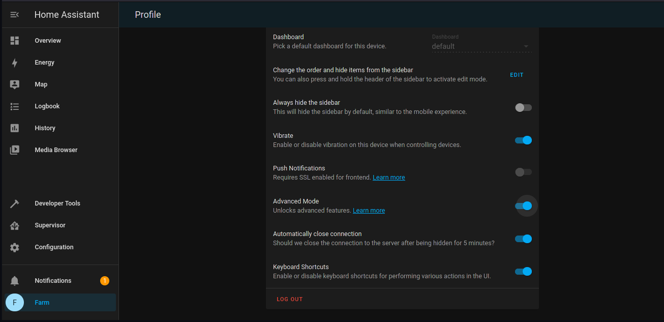
Enable Advanced Mode in User Settings of Home Assistant:
Go to Superviser - Add-ons and search for “InfluxDB” and chose the card.
Click on install and wait for it to finish.
Check all switches and start the application. In the logs you can find errors if it does not work.


If you encounter an 401: Unauthorized Error when opening the application from the sidebar:
Changing Enhanced tracking protection from strict to standard in firefox can solve the problem but using Google Chrome or a chromium based browser might allow the site to load.
Open InfluxDB dashboard from the sidecard and create a new database named “farm”

Allow the farmer user full acess to InfluxDB by typing in username and password and give all permissions

Install Grafana as done with InfluxDB from the Add-on store.
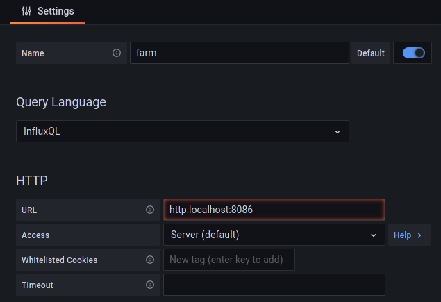
Open Grafana dashboard and add the newly added InfluxDB “farm” as new source.

Input all necessary infos into the text fields

ESPHome
https://esphome.io/
Install from Add-On store and start it like done with the other two applications.
Open ESPHome from the sidecard and create a new ESPHome Node
Enter Wifi SSID and password and chose ESP32 as platform

The basic configuration looks like this:

Click install and chose manual download

Let ESPHome compile the firmware and save it when finished

A installation of ESPHome Flasher is required to flash the firmware to the ESP32. The ESP32 should be connected via USB.
The software and install can be found here: https://github.com/esphome/ESPHome-Flasher
Alternatively the arch package can be built: https://aur.archlinux.org/packages/esphome-flasher
Run in terminal:
sudo esphomeflasher
Chose the binary file / firmware and click Flash ESP

When the process was sucessfull, the ESP32 will connect to the wifi and the ESPHome integration and will show as online. From there on easy OverTheAir updates can be sent to this node.

The devices and protocols that can be connected can be found documented here: https://esphome.io/#devices
To calibrate the sensor, this page is helpful: https://esphome.io/components/sensor/index.html#sensor-filters
Node1.yaml configuration of ESPHome Node with capacitive soil moisture sensor:
esphome:
  name: node1
  platform: ESP32
  board: esp32dev

# Enable logging
logger:

# Enable Home Assistant API
api:

ota:
  password: "farmerpassword"

wifi:
  ssid: "FritzBox7390U-R1"
  password: "492065679669!!R1"

  # Enable fallback hotspot (captive portal) in case wifi connection fails
  ap:
    ssid: "Node1 Fallback Hotspot"
    password: "farmerpassword"

captive_portal:

sensor:
  - platform: adc
    pin: GPIO35
    name: "Soil Moisture"
    unit_of_measurement: "%"
    update_interval: 500ms
    attenuation: 11db
    filters:
      - lambda: |-
          if (x > 3.25) {
            return 0;
          } else if (x < 1.46) {
            return 100;
          } else {
            return (3.25-x) / (3.25-1.46) * 100.0;
          }
      - median:
          window_size: 4
          send_every: 4
          send_first_at: 4
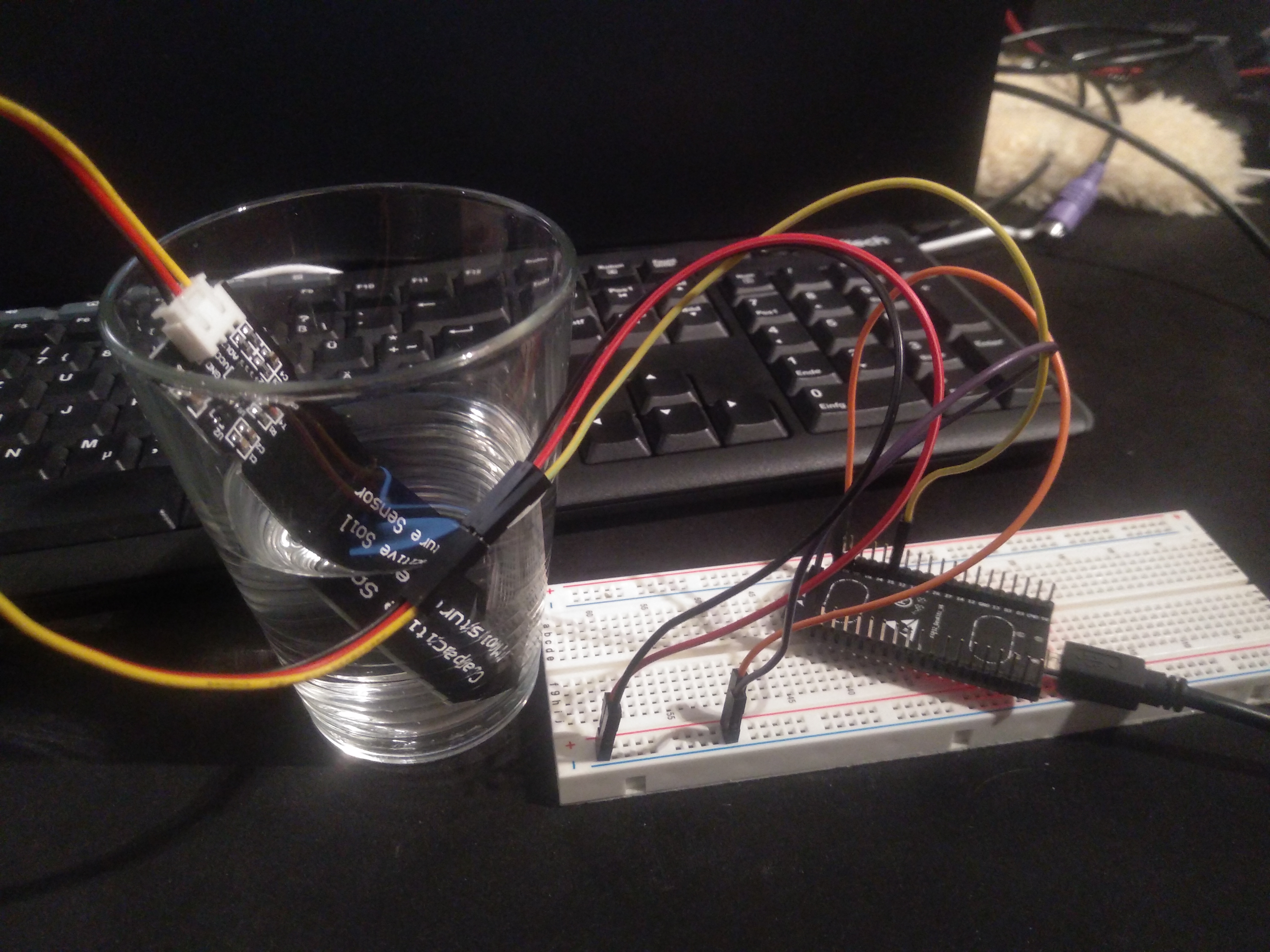
Measured voltage levels from Capacitive Soil Moisture Sensor:
- 3.25V when dry in air
- 1.46V when wet in a glass of water
Log output in ESPHome:

After sucessfull OTA install the node should appear as a new device found in the Home Assistant Integrations.
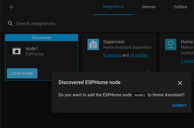
It can be added and will automatically be shown in the Home Assistant Dashboard / lovelace

Soil moisture sensor in a glass of water and removing it:
Install the File Editor Add-On to edit Home Assistant's configuration.yaml
Home Assistant configuration.yaml addidtion to store the HA sensor values in the influxDB:
influxdb:
  host: localhost
  port: 8086
  database: farm
  username: farmer
  password: farmerpassword
  max_retries: 3
  default_measurement: state
  include:
     entities:
        - sensor.soil_moisture
Afterwards the recorded values can be observed in the grafana dashboard displaying the graph for soil moisture.

4. Discussion
The system is not finalized and needs to expanded to work independantly of human input or observation.
The relay module is not added to ESPHome yet, but integration is simple.
The Gafana plot can be added to the Home Assistant dashboard for an easier overview of the current and past soil moisture values.
The automations and deciscion making algorithms need to be refined and expanded to ensure proper working autonomous farm operation.
There are already prebuilt systems for farming management or IoT cloud but building our own system from freely available software has given many insights on how the IoT infrastructure works and how to connect multiple devices to a central instance.
Our initial decision to use Home Assistant was also based on the premise to later add appliances that are commonly found in homes such as LED light panels that can be adressed via open standards like zigbee to make plant farming automation also acessible to normal people not wanting to invest in specialized equipment found in professional environments that might use different, more advanced protocols or systems.