Table of Contents
Group G: Rajshree Jeewon (26941), Raphael Komanek (23045), Daphne Larose (27571)
Automatic plant watering system for indoor greenhouses
1. Introduction
Water is of utmost importance for plants. It helps the plant to germinate, to undergo the process of photosynthesis in which energy is produced for the plant growth, for absorbing nutrients from the soil and also for the process of transpiration in which there is a continuous flow of water and nutrients from root to leaf. Over-watering and under-watering of the plants are two common mistakes which affects the plant growth. An automated water system delivers just the right amount of water that the plant actually needs. It enhances the water level according to the soil moisture and weather predictions for optimal plant growth using sensors or timers. Alert notifications can be received whenever the water level is low. The water pump system is linked with the moisture sensors and it is turned on and off as per the water requirements of the plants. Hence, the watering process is made more efficient.
Raising herbs and edible plants from seeds can sometimes be a difficult task. For instance, in Germany, the seasons can provide bad growing conditions for certain plants and herbs. A good idea would be to use a greenhouse as it provides protection from cold weather, rain, snow, temperature differences and too much sunlight. Some other factors that should be taken into consideration are regular watering, humidity, temperature and soil moisture which is essentially important for young plants as they are still developing and are as such more vulnerable.
The goal of this project is to provide an easier approach to said task. To accomplish this, different monitoring sensors, an ESP32, other devices, Grafana and Node-red are used. The project uses a humidity/temperature sensor and a soil moisture sensor for the measurement of certain factors. An ESP32 microcontroller is used in our project that connects all the different sensors and devices. It was also programmed to manage the different tasks, such as sending the data over Wi-fi. The transmitted data is managed with the programming tool Node-Red. In the end, the data is then represented in Grafana. Grafana is a web application for the visualization of data. This provides a long-term overview over the measurements that can safely be accessed over the internet.

Figure 1.0 A small portable greenhouse
2.0 Materials and Methods
2.1 Materials
- Espressif ESP32 DevKitC Wrover Module
- Grove Temperature and Humidity Sensor(SHT31)
- Capacitive Soil Moisture Sensor
- Submersible Water Pump and a 6V battery pack
- Relay
2.1.1 Espressif ESP32 DevKitC
ESP32-DevKitC is a low-power consuming, low-cost microcontroller board, with built-in Wi-Fi and Bluetooth that enable remote controlling and monitoring. ESP32 is also capable of handling other internal peripherals such as SPI (Serial Peripheral Interface) or I2C. Due its compatibility with Arduino IDE, it can be easily used by Libraries that can be installed. It can operate in a wide range of temperatures from -40°C to 125°C.

Figure 2.0 Espressif ESP32 DevKitC
2.1.2 Grove Temperature and Humidity Sensor(SHT31)
The Grove Temperature and Humidity Sensor is a highly reliable and accurate sensor with a quick response. The relative humidity has an accuracy of ±2% and ±0.3°C for the temperature. The SHT31 is compatible with 3.3 Volts and 5 Volts meaning it can be used both with the ESP32 and the Arduino UNO and also supports I2C communication. Furthermore libraries are readily available which facilitates the use. Just like the ESP32, the SHT31 can operate under temperatures ranging from -40°C to 125°C.

Figure 3.0 Grove Temperature and Humidity Sensor(SHT31)
2.1.3 Capacitive Soil Moisture Sensor
The Capacitive Soil Moisture Sensor Module is a low-power sensor that measures the difference in capacitance caused by the changes in the dielectric that is formed by the soil and the water. The sensor’s capacitance is measured by the use of a 555 based circuit (that is, it provides a single pulses over a long time) that produces a voltage proportional to the capacitor inserted in the soil. This voltage is after that measured by means of an Analog to Digital Converter which produces a number that we can then interpret as soil moisture. Due to the capacitive probe, corrosion is minimised and there is no electrical current flowing in the soil and no electrolysis is induced. It consists of 3 connectors; namely Ground, Voltage common connecter, VCC (3.3V – 5.5V DC) and the analog output that is usually connected to the analog input in the microcontroller.

Figure 4.0 Capacitive Soil Moisture Sensor
2.1.4 Submersible water pump
The 5V water pump was used together with the relay module and a battery pack that is being used to power the pump.

Figure 5.0 Water pump and battery pack
2.1.5 Relay Module
A Relay HLS8L-DC5V-S-C with a coil voltage(primary voltage) of 5V was used as an electrical switch to control when the pump turns on and off as the water pump has a higher voltage than the ESP32. The relay module acts like a bridge inbetween the water pump and the ESP32.
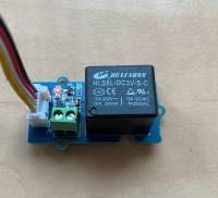
Figure 6.0 Relay Module
2.2 Software
2.3 Setup Overview
Figure 7.0 below shows how the different electronic hardwares have been connected to the GPIOs (general-purpose input/output) of the ESP32. The setup was created using the Electronic Design Automation software Fritzing.

Figure 7.0 Representation of how each components have been connected
Figure 8.0 shows the schematic diagram. It allows for a more comprehensive understanding of the circuit.

Figure 8.0 Schematics of the circuit
3.0 Results
3.1 Code
The code below includes the libraries used and shows how it was connected to Wifi and to MQTT for data transmission.
- Automatic watering system.ino
// Libraries that we used
#include <SPI.h>
#include <Ethernet.h>
#include <PubSubClient.h>
#include <WiFi.h>
#include <Wire.h>
#include <Adafruit_SHT31.h>


int soilmoisturevalue = 0; // for moisture value readings
char soilmoisturearray[16]; // to store the moisture value

float humidityvalue = 0; // for humidity value readings
char humidityarray[16]; // to store the humidity value

float temperaturevalue = 0; // for temperature readings
char temperaturearray[16]; // to store the temperature value

int PIN = 4; // the relay is connected to pin 4 on the ESP32

Adafruit_SHT31 sht31 = Adafruit_SHT31();

const char* ssid = "******"; // The network's name
const char* password = "*******"; // password for the network


const char* mqtt_server   = "hsrw.space"; // MQTT Broker IP address
const char* mqtt_username = "user";
const char* mqtt_password = "mqtt";

const char* myname = "rajshree";
const char* soilmoisture_topic = "/amc2021/rajshree/soil_moisture"; // topic to publish moisture values
const char* humidity_topic = "/amc2021/rajshree/humidity"; // topic to publish humidity values
const char* temperature_topic = "/amc2021/rajshree/temperature"; // topic to publish temperature values
const char* water_pump_topic = "amc2021/rajshree/water_pump"; // topic to turn on water pump based on the soil moisture values

void setup_wifi() {
  delay(10);
  // connecting to a WiFi network
  Serial.println();
  Serial.print("Connecting to ");
  Serial.println(ssid);

  WiFi.begin(ssid, password); //use the defined SSID and password

  while (WiFi.status() != WL_CONNECTED) {
    delay(500);
    Serial.print("."); // as long as there is no connection to the Wifi, print one dot with 500ms delay
  }

  Serial.println("");
  Serial.println("WiFi connected");
  Serial.println("IP address: ");
  Serial.println(WiFi.localIP()); // when the connection is established, print two messages and the IP of the Wifi
}
void callback(char* topic, byte* payload, unsigned int length) {
  Serial.print("Message arrived [");
  Serial.print(topic);
  Serial.print("] ");
  for (int i = 0; i < length; i++) {
    Serial.print((char)payload[i]);
  }
  Serial.println();
}

WiFiClient ethClient;
PubSubClient client(ethClient);

void reconnect() { //It will reconnect to the server if the connection is lost using a blocking reconnect function

  while (!client.connected()) {
    Serial.print("Attempting MQTT connection...");
    // Attempt to connect
    if (client.connect("arduinoClient", mqtt_username, mqtt_password)) {
      Serial.println("connected");

    } else {
      Serial.print("failed, rc=");
      Serial.print(client.state());
      Serial.println(" try again in 5 seconds");
      // Wait 5 seconds before retrying
      delay(5000);
    }
  }
}

void setup()
{
  Serial.begin(57600);

  setup_wifi();

  client.setServer(mqtt_server, 1883); //MQTT data transmission using port 1883
  client.setCallback(callback);

  delay(1500); // Allow the hardware to sort itself out
  Serial.println("SHT31 test");
  if (! sht31.begin(0x44)) {   // 0x44 is the i2c address
    Serial.println("Couldn't find SHT31");
    while (1) delay(1);
  }
  pinMode (PIN, OUTPUT); // sets digital pin 4(the relay) as an output

  client.subscribe (water_pump_topic); // subscribe to water pump topic
}

void loop()
{
  if (!client.connected()) {
    reconnect();
  }
  client.loop();

  reading_data (); // reading data from the different sensors from MQTT_publishing

  delay(2000); // delay by 2 sec


}
The code below is about the measurement readings and MQTT publishing.
- MQTT publishing.ino
void reading_data () {
  soilmoisturevalue = analogRead(34); // soil moisture reading connected to pin 34, an analog-to-digital converter pin on the esp32
  Serial.print("soilmoisture");
  Serial.println(soilmoisturevalue);

  String moisture = String(soilmoisturevalue); // for MQTT transmission
  moisture.toCharArray(soilmoisturearray, moisture.length() + 1);

  client.publish(soilmoisture_topic, soilmoisturearray); // the soil moisture values are published under the topic soil moisture

  temperaturevalue = sht31.readTemperature(); // temperature reading obtained by the SHT31 sensor
  humidityvalue = sht31.readHumidity(); // humidity reading obtained by the SHT31 sensor

  if (! isnan(temperaturevalue)) {  // check if 'is not a number', then convert to a char array
    String temperature = String(temperaturevalue);// for MQTT transmission
    temperature.toCharArray(temperaturearray, temperature.length() + 1);
    client.publish(temperature_topic, temperaturearray);// To publish the topic under

    Serial.print("Temp *C = "); Serial.print(temperature); Serial.print("\t\t"); // gives the temperature in degree celcius
  } else {
    Serial.println("Failed to read temperature");
  }

  if (! isnan(humidityvalue)) {  // check if 'is not a number'
    String humidity = String(humidityvalue);
    humidity.toCharArray(humidityarray, humidity.length() + 1);
    client.publish(humidity_topic, humidityarray); // the humidity values are published under the topic humidity

    Serial.print("Hum. % = "); Serial.println(humidity); // gives the humidity value as a percentage
  } else {
    Serial.println("Failed to read humidity");
}

if (soilmoisturevalue > 2800) {
  digitalWrite (PIN, HIGH); // if soil moisture value is higher than 2800, switch on the water pump
  delay(1000); // The pump is switch on for 1 sec until the moisture level drops below 2800
}
else {
}
digitalWrite (PIN, LOW); //Water pump turned off if soil moisture value is lower than 2800

}
Why the pump should be turned on when the soil moisture value is above 2800?
- Dry in open air = 3500
- Dry soil needing water = 2800 - 3100
- Moisture in a just watered soil = 1800
- Moisture in a cup of water = 1640
Based on that data, the program below defines the following ranges:
- Value < 1500 implies that the soil is too wet.
- Soil moisture between 1900 – 2600 is the target range.
- Soil moisture value > 3300 implies that the soil is dry enough and it should be watered.
3.2 NIG
For the documentation of the data measured, NIG (Node-red, Influxdb, Grafana) is used. The code for receiving data from our sensors are uploaded under three topics namely temperature, humidity and soil moisture in note-red and it is connected with influxdb in which all the data in this time series is incorporated in a single binary. The water pump topic is linked to the dryness level and an on or off function as it depends on the soil moisture whether the pump is turned on or off.
 Figure 9.0 Documentation of the data in note-red
Grafana is then linked with influxdb so that the data measured can be displayed in the forms of graphs.

Figure 10.0 Data measurement results in Grafana
4.0 Discussion & Conclusion
A graph was obtained for each parameter measured as can be seen in figure 10.0. The first graph on the left measured the temperature of the inside air of the greenhouse. The second graph on the right shows the humidity in the greenhouse as a percentage of the water vapour content in the air over time. If the temperature and humidity values are too high, the lid of the greenhouse can be removed as a high temperature is detrimental to plant growth and too much humidity causes the growth of mold and bacteria which in turn affects the development of plants. The last graph shows the data measured for the soil moisture with a dryness level on a scale of 0-100 over time and a higher value implies a drier soil. A scale of 0 to 100 was used instead of the original analog reading of 0 to 4095 to better analyse the soil moisture reading. As can be seen on the soil moisture graph above, the dryness level decreased. This is due to the activation of the water pump during which the soil was watered leading to a lower dryness level (higher moisture value). Whenever the soil dryness level is high, the water pump will automatically activate and water the plant until it reaches a desired moisture level.
4.1 Limitations & Improvements
At first, we tried using the DHT 11 and DHT 22 sensors for the measurement of the two parameters namely temperature and humidity which unfortunately did not give us any results and it seemed to be unreliable. We then switched to the Grove Temperature & Humidity sensor (SHT31) which gave us accurate results for the measurement of these two parameters. We also wanted to use the ultrasonic sensor to measure the water level but it required a voltage of 5V which is not supported by the ESP32 as it has a maximum of 3.3 V. In our project, we have a drip water system which waters one small pot at a time and the water tube has to be placed in each of the pots in order to water them. As an improvement for a better watering system, a sprinkler could be used instead to water the plants.
To conclude, the aim of this project which was to develop an automated watering system for plants in indoor greenhouses was achieved, regardless of the limitations, using the code, materials and methods mentioned above.
5.0 Video showing the project
References
- Unordered List ItemESP32 Espressif Systems 2021 https://www.espressif.com/en/products/socs/esp32
- Unordered List Item“Overview of ESP32 features. What do they practically mean?” Explore Embedded https://www.exploreembedded.com/wiki/Overview_of_ESP32_features._What_do_they_practically_mean%3F
- “Grove - Temp and Humi Sensor(SHT31)” Seeed Technology Co. Ltd https://wiki.seeedstudio.com/Grove-TempAndHumi_Sensor-SHT31/
- “Tutorial – Using Capacitive Soil Moisture Sensors on the Raspberry Pi” (2021)SwitchDoc Labs Blog, MH Magazine WordPress https://www.switchdoc.com/2020/06/tutorial-capacitive-moisture-sensor-grove/
- “ESP32 ADC – Read Analog Values with Arduino IDE” Random Nerds Tutorials https://randomnerdtutorials.com/esp32-adc-analog-read-arduino-ide/
- “ESP32 Relay Module – Control AC Appliances (Web Server)” Random Nerds Tutorials https://randomnerdtutorials.com/esp32-relay-module-ac-web-server/