amc2022:grouph:link
Table of Contents
Build
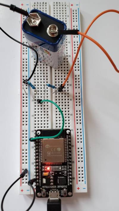
| figure 5.1 Setup showing the connections for battery voltage reading on ESP32 |
Schematics

| figure 5.2 Schematic for battery voltage reading |
Code & Description
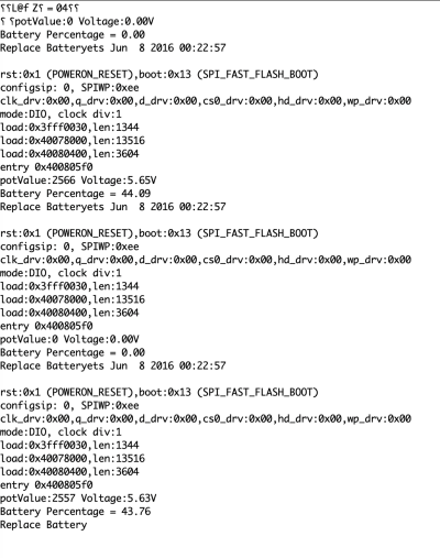
*//Reading of voltage is done by the Analog Pin reader.
*//Because the max input voltage on the pins is 3.3 V we cant directly read the 9V battery voltage.

 int potPin = A0;         // Analog pin has to be ADC 1, because ADC 2 are used by wifi and wont work
int potValue;
float voltage =0;         // float because its a decimal number not integer
float battery_percent;

void setup() {

  Serial.begin(115200);


  {

  potValue = analogRead(potPin);
  float voltage = (3.3/4095.0) * potValue * 2.73;


  *//Resistors and other components can have a varying number of outputs, although they are usually minimal
  *//additional calibration has to be done in order to get accurate readings
  *//We have found that the use of a multimeter will help in determining the values that will provide best outcomes
  *//Because we have different boards, resistors and setups, the final code could have alterations in the calibrating numbers

  Serial.print("potValue:");
  Serial.print(potValue);


*//While the serial monitor output can be changed, we are more interested is in the overall result which is transmitted
*//to Grafana for easy access


  Serial.print(" Voltage:");
  Serial.print(voltage);
  Serial.println("V");


  battery_percent = mapfloat(voltage, 3.0, 9.0, 0 , 100); // min value cut off at 6V and maximum voltage is 9V

  if (battery_percent > 100)
  {
    battery_percent = 100;
  }
  if (battery_percent < 0)
  {
    battery_percent = 0;
  }

*//For the conversion between the actual Analog reading to a percentage we use a mapFloat function
*//It uses the input range from the analog sensor to produce another set of useful values
*//float values will allows to get decimal numbers and a more accurate reading
*//We use a the min voltage value, then max voltage value, and min percentage and max percentage
*//Then we ask the program to give us the corresponding percentage value within the parameters


  Serial.print("Battery Percentage = ");
  Serial.println(battery_percent);


  if (voltage > 7.0 && voltage < 8.2)            // THIS VALUES HAVE TO CHANGE ACCOrDING TO SOURCE
  {Serial.print("Low bat");                      // USE VOLTMETER TO FIND THE ACCURATE VOLTAGE
  }
  if (voltage <6.5)                              //cut-off value is at 5.4V according to specification , we use 6V
  {Serial.print("Replace Battery");
  }
  delay(1000);


*//We have included a notification that will tell us what is going on with the voltage and overall battery status
*//We include a parameter that will produce 2 warning signs:
*// LOW BAT means that our battery is within 7 to 8.2V
*// REPLACE BATTERY means voltage has dropped below 6.5V, number obtained from data sheet

}
}

 float mapfloat(float x, float in_min, float in_max, float out_min, float out_max)
{
  return (x - in_min) * (out_max - out_min) / (in_max - in_min) + out_min;
}

*//here we include the parameters and equation that will serve as the backbone for the mapFloat function above.


void loop()
{

}


*// NO LOOP NEEDED,,, ONE VALUE WITH WARNING SHOULD BE DISPLAYED ON GRAFANA
Issues & Characteristics
The actual voltage will not be 100% accurate because the ADC pins have a non-linear behavior. This means according to the Figure # down below that, above a certain threshold the reading will produce equal inputs, thus we consider that from 3 to 3.3V the battery is at a 100% charge.
Additionally we can see that the discharge behavior of the battery we are using, which is a model 6F22 is a curve that has a specific equation, we could find the curve's equation and use it to better represent the discharge values, however since we plan to upgrade our battery system we purposely used a simpler version in our code to achieve good enough results.
 |  |
|---|---|
| figure 5.3 Graph depicting battery discharge for battery model 6F22 9v Source:https://www.mega-piles.com/im/PANASONIC-6F22-9V-CARBONE-ZINC_550.pdf | figure 5.4 Graph depicting ADC voltage VS reading behavior for ESP32 micro controller. Source:https://microcontrollerslab.com/adc-esp32-measuring-voltage-example/ |
Results
amc2022/grouph/link.txt · Last modified: 2022/09/10 00:51 by gustavo001