Micro:Bit Robot
We are using makecode to program the microbits.
Workarounds on Ubuntu
Unfortunately setting up the WebUSB mechanism needed to program the mircobits via USB from Chrome, Chromium or Edge on Linux is causing some trouble.
- Shreya's and copilot's howto: microbit_troubleshooting.pdf
Download the .sh (bash script) file below to your Downloads folder by clicking on the blue title.
- prep_microbit_on_ubuntu.sh
set -x
wget https://dl.google.com/linux/direct/google-chrome-stable_current_amd64.deb

apt update
apt install ./google-chrome-stable_current_amd64.deb -y
apt install google-chrome-stable -y

echo 'SUBSYSTEM=="usb", ATTR{idVendor}=="0d28", ATTR{idProduct}=="0204", MODE="0666"' > /etc/udev/rules.d/99-microbit.rules

udevadm control --reload-rules
udevadm trigger
Then follow the steps given here:
cd ~/Downloads
chmod 755 prep_microbit_on_ubuntu.sh
sudo ./prep_microbit_on_ubuntu.sh
Goal
Building our own micro:bit robot kit.
Requirements:
- powered by a mini 5V USB powerbank (e.g. 2000 - 3000 mAh),
- The Micro:Bit power input is 3.3V regulated, via the 3V skrew connector (conductive holes),
- driving two SG90 micro servo motors (360°) with wheels (not the yellow DC motors), powered by 5V
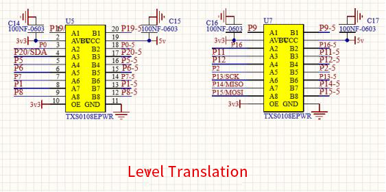
- level shifter for the servo control signal from Micro:Bit 3.3V to 5V for the servos
- driving at least one additional servo motor (360° or 180°) for further action,
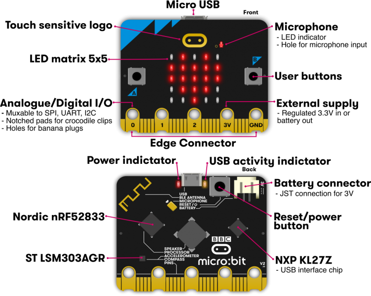
The Micro:Bit Board - Info from Keystudio
Pictures from the Keystudio Wiki:
https://wiki.keyestudio.com/MB0102_Keyestudio_Microbit_Main_Board_%2BUSB_Cable%2BBattery_Holder_with_Batteries
Micro:Bit V2 Schematics
Main LDO and Regulator Circuit: NCP114
NCP114
- out: Vout = 3.3V fixed,
- in: Vin = 5.5V max,
- current: Imax = 300mA
- datasheet: NCP114BMX330TCG
Micro:Bit Regulator Circuit
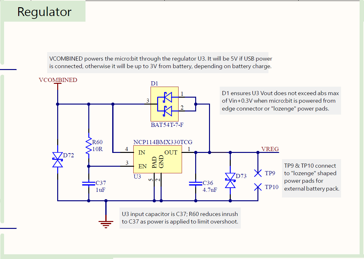
NOTES:
Read the annotations on the regulator schematic! The board can have FOUR power input sources.
- 5V USB via USB connector
- 3V - 4.5V via battery connector (skrew terminals)
- “lozenge” (Pastille, Raute) shaped power pad, connected to Vout of NCP114
- 3V - 5V typ. from edge connector
Findings
 It is weird that the power input from the edge connector is directly connected to the voltage output pin of the LDO! Do I (rb) understand this correctly?
Compass and Accelerometer: LSM303AGR
Expansion Boards / Parts
BBC micro:bit GPIO Expansion Board/Adapter
- no power regulator
- no motor drivers
- just a buzzer
- works for V1 and V2


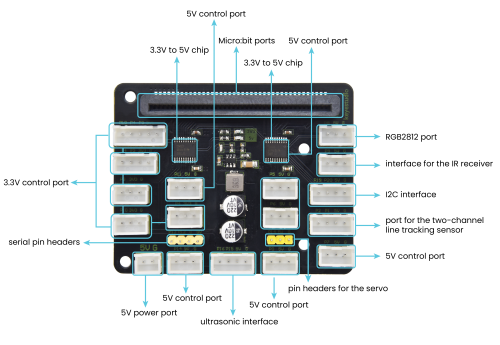
Keystudio KS4030
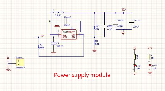
- voltage regulator 5V → 3.3V
- logic level shifter
Monk Makes Micro:Bit Servo Controller Board
ATTENTION: 180° ONLY!
Original source: https://www.monkmakes.com/mb_servo_kit
Distributors:
RS Online: https://de.rs-online.com/web/p/bbc-micro-bit-add-ons/2048260
RobotShop: https://eu.robotshop.com/products/servo-controller-microbit-monk-makes
okdo: https://www.okdo.com/de/p/servo-kit-for-microbit/


Kitronik Simple Servo Control Board
Original source: https://kitronik.co.uk/products/5673-kitronik-simple-servo-control-board-for-bbc-micro-bit

Distributors:
- …
Kitronik Compact 16 Servo Driver Board (PCA9685 I2C PWM driver IC)
Original source: https://kitronik.co.uk/products/5694-compact-16-servo-driver-board-for-the-bbc-micro-bit
Datasheet:
5694-kitronik-compact-16-servo-driver-board-for-microbit-datasheet.pdf
Datasheet of PCA9865 at NXP:
PCA9685.pdf
Adafruit tutorial on PCA9865:
https://learn.adafruit.com/16-channel-pwm-servo-driver/overview
Features:
- Operating Voltage (Vcc): 3V to 12V
- Number of Servo channels: 16
- Servo Voltage: Same as input Voltage
- Max continuous current (all servos): 10A

SG90 Micro Servo Motor 9G
ATTENTION: 180° ONLY!
Distributors:
AZ-Delivery: https://www.az-delivery.de/en/products/az-delivery-micro-servo-sg90?variant=12236813336672

Technical Infos / Video Tutorials
Servo Motors
| Servos - Funktionsweise und Eigenbauten |
| Servos - working principle and homemade types |
| Using Servo Motors with Arduino |
Other Topics
| Funktionsweise von Kippstufen |
| Flip-flop / multivibrator |
| Pulsweitenmodulation (PWM) |
| Pulse-width modulation (PWM) |