Table of Contents
Sensors and Communication
Welcome to Day 2 of our IoT Workshop! Today, we'll take a closer look at sensors, the backbone of IoT data collection. You'll gain insights into how sensors operate and discover key protocols like Analog, OneWire, and I2C that facilitate communication between devices and sensors. This foundational knowledge will empower you to effectively utilize sensors in your IoT projects.
1. Output - PWM
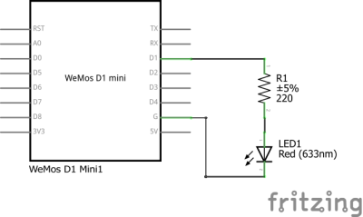
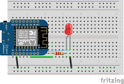
Now, we're stepping into the practical aspect of our workshop, focusing on Pulse Width Modulation (PWM) output with the ESP8266. PWM isn't just about adjusting the brightness of an LED; it's a versatile method of communication. Through this segment, you'll grasp how PWM operates as a form of control, allowing us to transmit information using varying pulse widths. This will come to life as we demonstrate PWM in action, using an attached LED as an illustrative example.
 Fig. 1: ESP8266 with LED - Schematic
 Fig. 2: ESP8266 with LED - Breadboard
2. Libraries
In the dynamic landscape of Arduino development, libraries play a pivotal role, especially when it comes to effective communication with sensors. These compact packages of pre-written code provide an invaluable resource, simplifying the process of interfacing with various sensors and components.
For IoT enthusiasts and makers, libraries serve as a bridge between complex hardware and user-friendly coding. By abstracting the intricate details of sensor communication, libraries empower you to focus on the application logic rather than low-level protocol intricacies.
Remember, in the Arduino world, libraries are your trusted companions, facilitating smooth communication and opening doors to limitless possibilities.
Good-To-Know: Most libraries come with examples that can get you started quickly.
3. Inputs / Protocols
3.1. Analog sensors (ex. capacitive soil moisture sensor)
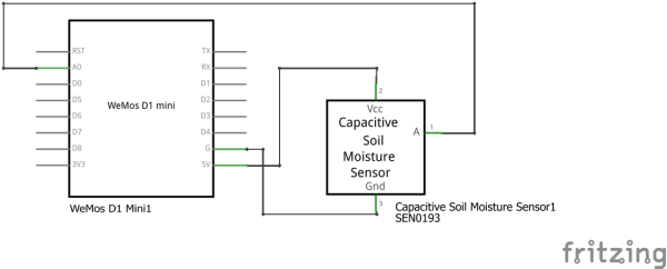
Through a special circuit, the sensor is able to translate from the soil moisture around it to an analog output voltage. The sensor consists of a PCB with a long thick trace on one end. If you want to learn more about this sensor you should read the following article: How Capacitive Soil Moisture Sensors Work by rbaron.
With these common sensors, we don´t need to reinvent the wheel. There are plenty of good tutorials out there on how to use this sensor. One we link here: Capacitive Soil Moisture Sensor - DFRobot Wiki There you will be able to learn how to integrate the sensor into your software as well as how to use it in the real world. Just keep in mind the electronics on top are not protected from the environment. Water shouldn't touch that part!
 Fig. 3: Wiring of the analog sensor
 Fig. 4: Schematic
We also prepared a little sketch for you. Try to understand it. A good way to do so is to look up function documentation in the Arduino Documentation:
- read-analog.ino
// the setup routine runs once when you press reset:
void setup() {
  // initialize serial communication at 115200 bits per second:
  Serial.begin(115200);
}

// the loop routine runs over and over again forever:
void loop() {
  // read the input on analog pin 0:
  int sensorValue = analogRead(A0);
  // Convert the analog reading (which goes from 0 - 1023) to a voltage (0 - 3.2V):
  float voltage = sensorValue * (3.2 / 1023.0);
  // print out the value you read:
  Serial.println("voltage: " + voltage);
  Serial.println("value: " + sensorValue);

  delay(1500);
}
3.2. 1-Wire (ex. temperature sensor)
One-Wire is a bus protocol that is heavily used by the company Maxim Integrated. One of the most popular sensors using this protocol is the (deprecated) DS18B20. It is an easy-to-use temperature sensor, that is available in multiple different form factors. In this workshop we use two different variants:
- Water-Proof DS18B20
- DS18B20 on a PCB
The DS18B20 needs in a minimal setup at least one resistor between its data line and the high potential. The first variant we mentioned doesn´t come with this included so it needs to be added on the breadboard. The second one has it already on its PCB included so it is a bit easier to integrate.
Here you can find some information that might be interesting for you, including a Datasheet for the sensors (if you get a new sensor → READ THE DATASHEET), a more detailed look at the OneWire Protocol, and last but not least a Library that you can use to integrate the sensor in your system:
Task: Try to get to research how to use the sensor with your MCU, regardless of which variant you have available.
3.3. I2C (ex. ToF sensor)
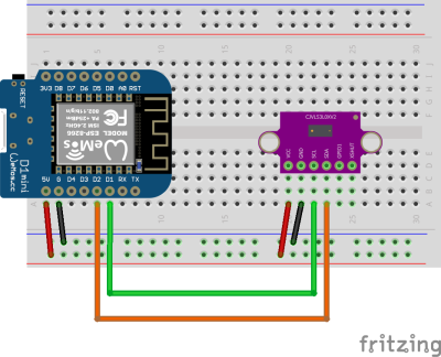
I2C is one of the most common sensor bus interfaces used. It requires 2 cables for communication. One is called SCL and the other is SDA. I2C in general is a serial interface. SCL is the serial clock. This is needed to synchronize the communication between two components. SDA is the actual serial data line. Here is where all the magic is happening. On one I2C bus, 127 slave devices can be attached. Therefore I2C is a master-slave protocol. The master will instantiate communication by calling for a specific address followed by a register it wants to read or write to, followed by some additional data in case of writing to a device. The slave device will give a response depending on the function called.
The sensor used in the sensor is a ToF sensor called VL53L0X, which is able to measure distance pretty accurately.
Have a look at the datasheet and the library:
- Here you can find a library for the sensor: Adafruit VL53L0X
Task: Try to get the sensor to work with your microcontroller.
3.3. Good to know
Out there are more than just the protocols that we covered today. Here are some more that are worth researching if you are interested:
- SPI
- UART
- Digital Interrupts

