Table of Contents
The idea behind this project is to provide a base platform that can be used in different visual monitoring activities. First, it was needed in a birdhouse project where a birdhouse should be monitored over an extended period.
Here are the goals that we try to hit with this project:
- a rather small footprint (should fit in the top of a birdhouse)
- Wifi capable
- good enough image quality (photo) so you can actually identify something
- solar chargeable
- night vision
- useable for other projects and also workshops
Technocal Development
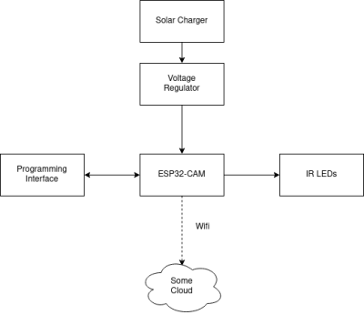
Block concept
First prototype
As a base platform, the known-working ESP32-Cam was chosen. But shortly after making the first prototype based on it, a couple of flaws were discovered. The prototype had a PCB which allowed plugging in multiple daughter boards together to make one complete system. Furthermore, it also included some IR LEDs to enable night vision. The main problem was the ESP32-CAM board itself. It works okay on its own, but it is harder to implement in another system. For example, we had to desolder the onboard flash led because it was not needed and consumed way too much power. Also was it hard to program the board because of the programming buttons which were located on the wrong side of the PCB. So there was more soldering and hacking involved than what should be needed. In the end, the prototype worked but we knew that we had to improve upon that.
!!Photo missing!!
Besides the hardware, a small NodeJS Server was developed which was able to get images from the ESP32 and save it on a server.
Second prototype (WIP)
The second prototype is currently a work in progress.
The main idea with this one is to combine the known working features of the first prototype on one single PCB. Because most of the used components have open-source schematics, these could be used as a base for the new custom PCB. So all the blocks got rebuilt on a new PCB. Only the voltage regulation part was built from scratch with newer components. Here you can see the end result:
!!Photo missing!!
Unfortunately, the board currently has two flaws. First of all the footprint for the solar charge controller is wrong. So the board was first not even able to power on. With bridging two pins at least the USB-power part could be restored for further testing. This has to be changed in a second version. The bigger flaw is the following: The board can be programmed (at a lower speed than usual) but the code is never executed. Further investigations have to be done.
Online Viewing Software
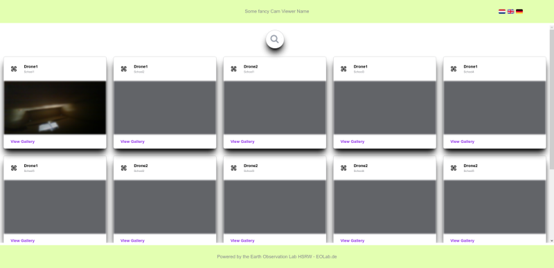
After starting the development of the second prototype we also started working on an open-source platform to view all the photos gathered by deployed versions of the hardware. In general, the software is built so other authenticated devices could upload photos as well.
Application
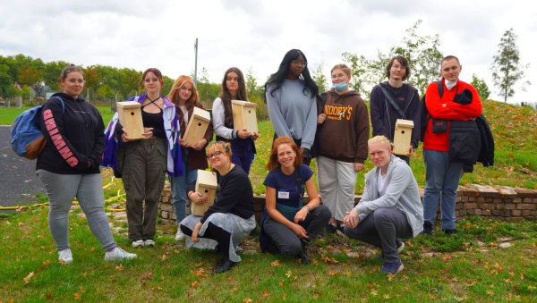
We use this open-source Wifi Camera in combination with a self-built birdhouse in workshops with students from local schools.
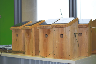
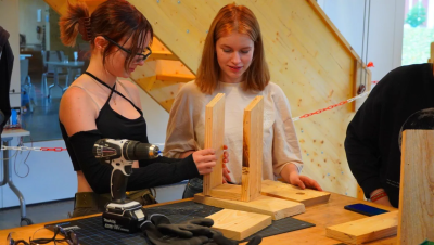
In the first part of the workshop, they will be given the pre-cut wood material and they have to screw it together. Furthermore, they can take these home and for example also paint them. The birdhouse is designed to be simplistic and the hole size for the bird is chosen for smaller local birds. At the top of the house is enough room to accommodate the electronics and a battery. In the second part of the workshop, the students will get an already populated PCB of the Wifi-Camera, except that two through-hole resistors are missing. They then learn how to solder and some basic applied electronics. After that, we go into the fundamentals of microcontroller programming, so what different kinds of IO pins there are, and how to use them. As a basic example, the students get the task to program a traffic light with 3 LEDs. Then the students will program an example web server code for the camera onto the microcontroller. With this, it is easily visible how the different camera parameters affect the taken image in the end.
In the end, the students will program the already written code for the camera and assemble the birdhouse with the electronics. They can then take the birdhouses with them and hang them up at their school or even at home. The automatically taken images are then visible in the aforementioned online viewing software.
With these workshops, which usually take around 5 to 6 hours, we hope to give the students an inside into our work, ranging from (digital) manufacturing at our FabLabs to the electronics design and at the end to microcontroller programming. The responses we had with these workshops were positive and engaging.
__Further Development!__
In this part, we are working on the integration of the Camera in a PCB and mounted inside the Bird Box.
What does the PCB consist of? Before answering this question, I would like to give you a look at how the PCB was developed.
First, we identified the goal. We want an electronic device that takes pictures in the dark (as inside the box during night it's almost complete darkness) and then uploads these photos to an online server (or in the current case to an Email) to be analyzed.
Then we need a Camera, and in our case, the ESP32-S3 XIAO Sense was a good option as it's very small, has low power consumption, includes a Wi-Fi module, and it's relatively cheap, costing around 13€. In the following table, you will find a list of parts used to develop this PCB.
| Part | Number | Price € | Provider |
|---|---|---|---|
| ESP32-S3 XIAO Sense | 1 | 36 | Amazon.de |
| IR333-A IR LED | 4 | 0.49 | Everlight Electronics Co Ltd |
| BD139 NPN Transistor | 10 | 6 | Amazon.de |
| Solar Charger BQ24074 | 1 | 14.20 | EXP tech |
| DC Battery 3.7V 2200 mAh | 1 | 17 | Amazon.de |
| Resistors | 100 | 6 | Amazon.de |
| Solar Cell | 1 | 6.65 | reichelt.de |
*So let's first speak about some parts separately.*
- ESP32-S3 XIAO:
This board is being offered by Seeed Studio. The Seeed Studio XIAO Series are diminutive development boards, sharing a similar hardware structure, where the size is literally thumb-sized. The code name “XIAO” here represents its feature “Tiny”, and the other half will be “Puissant”. Seeed Studio XIAO ESP32S3 Sense integrates a camera sensor, digital microphone, and SD card support. Combining embedded ML computing power and photography capability, this development board can be a great tool to get started with intelligent voice and vision AI.
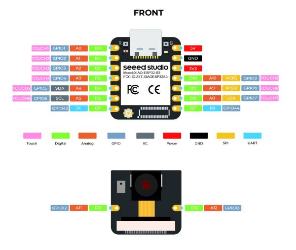
Here you can see the Pinout for the board:
| As you can see, it comes in two parts which can be attached together, one part has the SoC (System on chip) and the other part has the Camera, Microphone, and the SD-Card slot. |
I have used Arduino IDE version 2.3.2 to upload the code to the board, but you have to adjust the IDE in a way so you can upload the code to the board without any errors. So, please do the following steps:
1. From Arduino IDE, go to Tools-Board-Boards manager
       a. Arduino ESP32 Boards v2.0.13
       b. esp32 v3.0.2 it only works on this version
2. From Arduino IDE, go to Tools-Manage Libraries
       a. ArduinoHttpClient 0.6.0
       b. Arduino_ESP32_OTA 0.3.0
       c. ESP32 Mail Client 3.4.19
Here is a link for the code as I have uploaded all the files on a github repo. https://github.com/msherif503/ESP32S3_Take-photo_Send_Gmail.git

