Table of Contents
Group N: Jonas Zender (21125) and Nepomuk
Garden Pond Monitoring Station
1. Introduction
In environmental monitoring different environmental parameters are measured in a systematic way to gain an insight into the processes going on in the environment. The aim is not only to better understand the complex world that surrounds us, but also to track the long-term development of for example ecosystems as it can help to register alarming trends and changes early on such that appropriate actions can be taken. This makes environmental monitoring a topic of uttermost importance in the times of global climate change, environmental pollution and continuously growing industry and population counts which all affect the Earth in manners that are not yet fully understood.
The temporal and spatial resolution of environmental monitoring can vary vastly, from annual measurements to continuous monitoring and from only a few square meters to entire continents. Typically monitoring parameters can be classified into secondary and primary environmental factors. While primary environmental factors are usually single, self-contained parameters such as temperature, humidity, pH or light availability, secondary environmental factors are a more complex combination of primary factors, for example climate or soil quality.
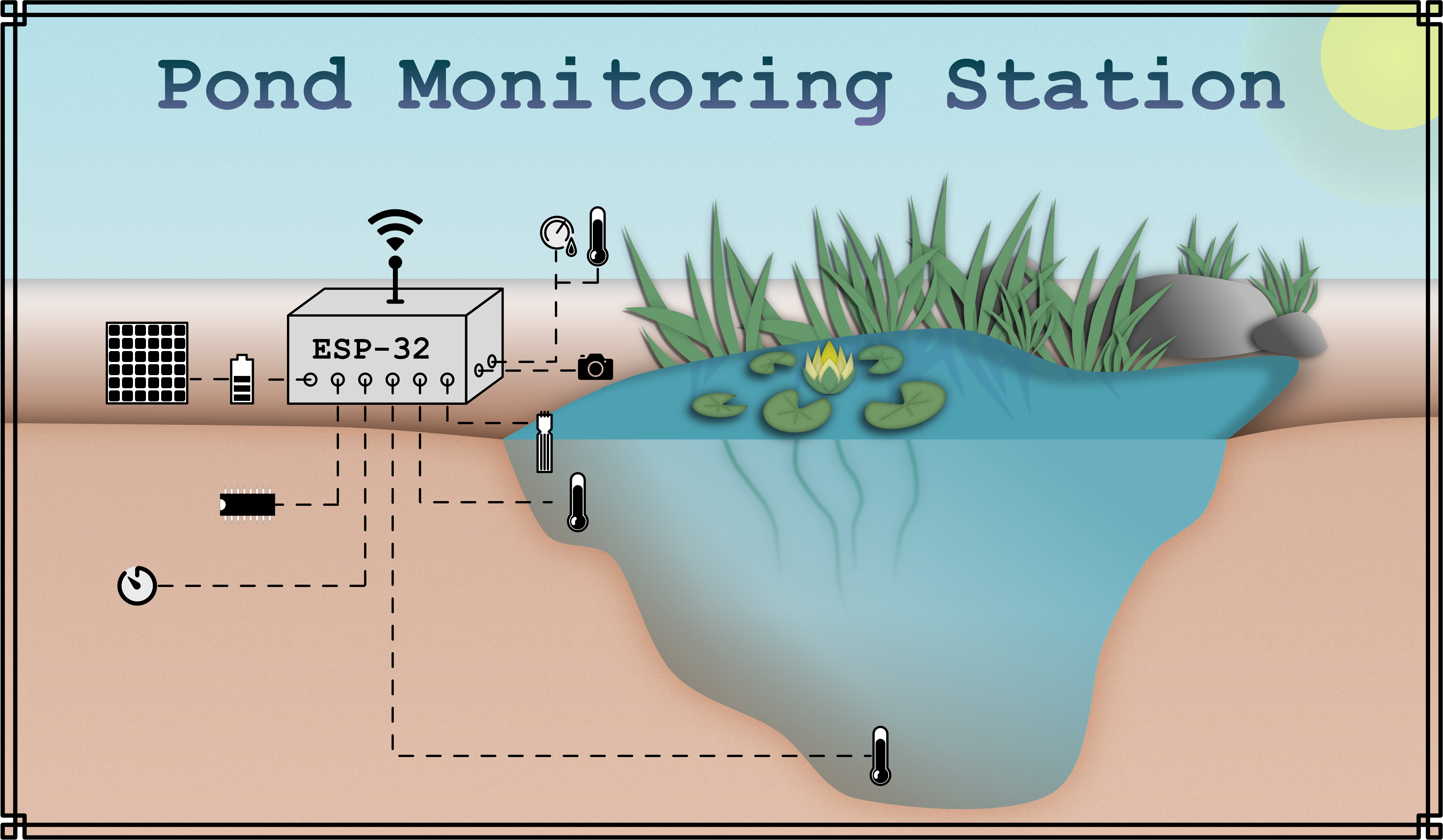
Microcontrollers are a valuable tool for all kinds of applications in environmental monitoring as they are small, cheap and easy to use, while offering the possibility to read the results of all kinds of sensors and transmit the data to databases where it can be assessed to draw valuable conclusions from it. The aim of this project was to design and program a small monitoring station for my garden pond to learn how such a system works and how to set it up.
Figure 1 shows a schematic on the complete station with all the aforementioned features installed and running. Click on the different parts of the station in the image to get further information on the modules (not all pages created yet).
2. Materials and Methods
The materials and methods section on the main page only gives a short overview about the different sections and parts of the project. For the complete description, please follow the links to the detail pages:
2.1 Microcontroller
The core of the monitoring station is the 32-bit ESP32 DevKitC-VB which is an inexpensive yet powerful microcontroller board. Besides having a fast processor and decent memory capacities, it also offers a lot of other advantages, most importantly it supports WiFi and Bluetooth which makes it particularly useful for Internet of Things (IoT) applications like the pond monitoring station. Furthermore, it offers a lot of possibilities due to its large number of GPIOs which can be used for the ESP32’s peripherals like SPI, I2C, I2S, UART, ADC, DAC, PWM or touch sensors. Another advantage is, that after installing the ESP32 boards manager, it can be programmed using the Arduino IDE and can use most of its libraries with only little changes. The ESP32 is thus capable of communicating with a large number of different devices like sensors making it very flexible and was therefore a good choice as a microcontroller for this project.
2.2 Air Temperature and Humidity Measurement
- Detail Page:
To measure the air temperature and the humidity by the pond, the DHT-22 was chosen as sensor. The DHT-22 senses the temperature through a thermally sensitive resistor (thermistor) which reacts in a predictable and reproducible manner to temperature changes. By measuring the resistance of the thermistor, the temperature can be determined. To sense the relative humidity of the air, it uses a capacitive humidity sensor. The sensor consists of a capacitor which uses the air on its contacts as a dielectric. As the dielectric constant of air changes with its humidity, it changes the capacitance of the sensor. By measuring the capacitance, it is possible to calculate the corresponding relative humidity of the air.
The sensor uses 1-Wire communication to transfer data between the sensor and the microcontroller (MCU); but as it does not have a unique address, only one sensor can be connected to each GPIO of the MCU. The advantage of the sensor is that it is cheap yet decently accurate. It just needs to be connected to the 3.3V power supply of the ESP32 and its data pin to one of the ESP32’s GPIOs. Reading the sensor data can easily be done using the DHT.h library but depending on the setup and configuration there are some things to consider like the sampling rate, instable phase or the necessity for pullup resistors for long data lines.
In the project the sensor was used to measure both temperature and humidity a number of times and average the results to gain the most accurate value. During testing, the DHT-22 delivered plausible results and reacted quickly to changes in its environment.
2.3 Water Temperature Measurement
- Detail Page:
The DS18B20 is a digital temperature sensor which comes in different packages, one of which being mounted inside a waterproof metal probe with a cable (1m) attached to it, which made it optimal for measuring the temperature in the pond. For measuring, two DS18B20s were used, one for measuring the temperature of the water close to the surface of the pond, and another for measuring at the bottom. This way it is possible to track how the sun’s irradiance (or its absence) influences the temperatures in different locations and how the values develop over the course of a day.
It uses a 1-Wire communication protocol, but in contrast to the DHT-22, each device that can communicate with this protocol has a unique 64-bit address, such that each sensor can be addressed individually. Therefore, it is possible to connect a huge number of sensors and read their data using only a single GPIO of the MCU. Like the DHT-22, it has an open-drain output which means that a pullup-resistor is necessary; the DS18B20 has no internal pullup resistor, so an external one is needed. But as all the sensors can be in the same data-bus, only a single pullup resistor is necessary for the whole data bus.
The DS18B20 also has the option to configure the measurement resolution from 9 bits to 12 bits. A lower resolution saves time during measurement but compromises the accuracy of the results. As measurements are only taken hourly, not continuously, the highest resolution was chosen as decreasing the measurement time was not as important as yielding accurate results. After determining the sensor’s addresses, test measurements were taken which were in line with those of the DHT-22.
2.4 Measures to Save Electricity
Later on, the station should run on a battery that is recharged using a PV-module. If the sun is not shining the electricity produced by the PV-module is impaired; therefore, the battery needs to be of an appropriate size to overcome these unreliable phases and the PV-module needs to be big enough to be able to recharge the battery again when the sun shines. To reduce the necessary capacity and size of the battery and the PV-module, the electricity consumption by the station should be reduced to a minimum.
All of the sensors have a current going through them, draining the battery, even when they are in stand-by and not measuring; especially the DHT-22. Even though the current is low, it sums up to a significant amount over the span of a day. To reduce this current, an SN74HC595(N) shift register was used to only supply a voltage to the sensors VDD pins when they are used to measure. A shift register receives a serial input and converts it to a parallel output on its 8 output pins. The shift register itself also draws a small current, but it is lower than that of the sensors.
The advantage of the shift register is, that it can be cascaded and therefore allows the MCU to control a large number of outputs while occupying only 3 GPIO pins. The efficiency of this method increases with the number of sensors connected and when the stand-by current of the sensors used is rather high. However, if a sensor draws more than approximately 5 mA, the voltage on the pin drops and might cause the sensor to stop working. This can be bypassed by connecting the shift register’s parallel output pin to the base of a transistor and connecting the sensor to it.
Managing the voltage supply of the sensors is one method for saving energy. However, most of the battery’s charge is drained by the microcontroller itself. To further reduce the electricity consumption the ESP32 can be put into deep sleep mode which consumes several thousand times less energy than leaving it idle in active mode. To wake it up once an hour as accurately as possible, an external interrupt issued by an accurate real time clock is the best method. The DS3231 is such an RTC module and provides the option to set two alarms and different alarm rates from once per second to once per month. It uses the I2C protocol to communicate with the MCU. After the initial setup, that means configuring the time and alarm registers, the only necessary communication between the RTC and MCU is the reset of the alarm. After the alarm register matches the time register, an alarm is triggered constantly by pulling the SQW pin low, which wakes up the ESP32 from deep sleep. To stop the signal and reset the alarm, the MCU needs to reset the alarm flag in the DS3231’s status register using I2C. For testing purposes, the alarm rate was set to once a minute which worked well. For the final setup, the RTC alarm needs to be configured to the once an hour alarm rate.
2.5 WiFi and MQTT
- Detail Page:
To send the measurement results to a server, the ESP32 was connected to a local WiFi network. The protocol used for transmitting the data is called MQTT (Message Queuing Telemetry Transport) and is a publish-subscribe network protocol for transporting messages between different devices. It was first developed in 1999 and is very popular for IoT (Internet of Things) applications.
The core of an MQTT network is a server also called MQTT broker. Other devices, called clients, can connect through WiFi to the broker and publish or subscribe to certain topics. The broker receives the messages that are published by the clients and sorts them by their topics. Clients can also subscribe to topics; if a new message is published under a certain topic, the broker redirects this message to all clients that are subscribed to that topic.
The ESP32 works as a client to the broker and publishes the sensor readings under their respective topics. For testing, a local mosquito server was used as broker and MQTT.fx as a client to subscribe to the topics and display test values. After the successful testing, the real sensor data was sent to the server of the university acting as MQTT broker. To store the data and print it, a combination of node-RED, influxdb, and Grafana (NIG) was used. Node-RED is an MQTT client that subscribes to the topics under which the sensor data were published and then uses a plugin to input the data to a connected influxdb database. In this time-series database, the data is stored permanently. Lastly, the values were extracted from the database and visualized using Grafana which is a web application for displaying data using charts, graphs, tables etc. in different panels.
2.6 Setup of the Station
After testing all the components individually, they were setup together as described in detail on their respective pages. For better understanding, figure 2 shows a graphic on how to connect the ESP32 and the other different modules and parts. To power the station, the ESP32 needs to be connected to a voltage supply, either by connecting to the MCU’s micro-usb-b connector or by supplying 5 V to the Vin pin. The board can also be powered with only 3.3V; however, this was not done here to decrease the chances of a brownout of the ESP32 in case of current spikes, for example during the establishment of a WiFi connection.
 |
|---|
| Figure 2 Graphic on how to set up the ESP32 and the modules and parts. |
For a better comprehension of the connections between the ESP32 and the different modules, the circuit diagram from figure 3 should be used as it also displays the designations of the different pins.
 |
|---|
| Figure 3 Schematic of the connections between ESP32 and the modules and parts. |
3. Results
The test results of the individual project sections can be found on the detail pages. After experimenting with the different modules and functions, their respective codes were combined to give the complete program code:
3.1 Code
- ESP32_Pond_Station.ino
//ESP32 Pond Monitoring Station V1.0

/***********************************************************************
 * 1. Deep Sleep, WiFi and MQTT Libraries/Definition/Variables...
***********************************************************************/
//WiFi and MQTT
#include "WiFi.h"
#include "PubSubClient.h"

//Local Wifi
const char* password = "******************";
const char* ssid = "*********";

//MQTT Server
const char* mqtt_server   = "hsrw.space";
const char* mqtt_username = "****";
const char* mqtt_password = "****";
const unsigned int mqtt_bufsize = 100;
const char* myname = "GroupN";

WiFiClient espClient;
PubSubClient mqttClient(espClient);

char Buffer[5];

//Deep Sleep
#include <Wire.h>
#define DS3231RTC_I2C_ADDRESS 0x68
#define I2C_SDA 21
#define I2C_SCL 22

//EEPROM
#include <EEPROM.h>
#define EEPROM_BYTES 2
#define WIFIRESETADDRESS 0
#define MQTTRESETADDRESS 1

//Restart
#define RestartPin 27

/***********************************************************************
 * 2. DHT-22
***********************************************************************/
//Definitions and Pins
#define DHTTYPE DHT22         //define the DHT-xx sensor
const int DHTPIN = 15;        //define the Data Pin (GPIO 2)

//Libraries & Objects
#include <DHT.h>

DHT dht(DHTPIN, DHTTYPE);     //Represents sensor

//Variables
float dht22AirTem = 0;        //takes up new readings + final average
float dht22AirTemSum = 0;     //takes up the sum of readings for averaging
String dht22Temperature = ""; //gives back Temperature as a String for MQTT Transmission

float dht22RelHum = 0;        //takes up new readings + final average
float dht22RelHumSum = 0;     //takes up the sum of readings for averaging
String dht22Humidity = "";    //gives back Humidity as a String for MQTT Transmission

const uint8_t AveragingNumberDHT22 = 5; //Number of measurements to be averaged

/***********************************************************************
 * 3. DS18B20
***********************************************************************/
//Definitions and Pins
const int ONE_WIRE_BUS = 14;      //=GPIO 14 of the ESP32 as 1-Wire Bus

//Libraries and Objects
#include <OneWire.h>            //Library for the 1-Wire protocol
#include <DallasTemperature.h>  //Library for sending commands and receiving data

DeviceAddress bottomSensorAddress = {0x28,0xC4,0xA0,0x51,0x38,0x19,0x01,0xC2};    //Address bottom sensor (sensor 1, Tape)
DeviceAddress surfaceSensorAddress = {0x28,0x0B,0xDB,0x60,0x38,0x19,0x01,0xA3};   //Address surface sensor (sensor 2, w/o Tape)
OneWire oneWire(ONE_WIRE_BUS);          //Object representing the 1-Wire bus
DallasTemperature DS18B20(&oneWire);  //Object representing the sensors

//Variables
float bottomTem = 0.00;         //for Temperature readings
String bottomTemperature = "";  //for the Sring to be sent using MQTT

float surfaceTem = 0.00;
String surfaceTemperature = "";

const uint8_t AveragingNumberDS18B20 = 5; //Number of measurements to be averaged

int RESOLUTION = 12;      //Resolution of the sensor
int TCONV = 750;          //Conversion time for resolution = 12
int delayTime = (TCONV/pow(2, (12-RESOLUTION))) + 10; //Necessary delay time after measuring to get new values, depending on resolution

/***********************************************************************
 * 4. 74HC595 Shift Register
***********************************************************************/
//Shift Register Pins
const int LATCHPIN = 2;
const int CLOCKPIN = 4;
const int DATAPIN = 0;

//Shift Register Pin Array
byte sensor_numbers[9] = {
  B00000000,  //all off
  B00000001,  //Pin 1
  B00000010,  //Pin 2
  B00000100,  //Pin 3
  B00001000,  //Pin 4
  B00010000,  //Pin 5
  B00100000,  //Pin 6
  B01000000,  //Pin 7
  B10000000,  //Pin 8
};

/***********************************************************************
 * 5. Main Program
***********************************************************************/

void setup() {
  //Reset Alarm & Enable Connection
  Wire.begin(I2C_SDA, I2C_SCL);
  clearAlarm1();
  EEPROM.begin(EEPROM_BYTES);
  Serial.begin(115200);
  esp_sleep_enable_ext0_wakeup(GPIO_NUM_13,0);
  WiFiConnect();
  MQTTConnect();

  //Setup Pins
  pinMode(LATCHPIN ,OUTPUT);
  pinMode(CLOCKPIN ,OUTPUT);
  pinMode(DATAPIN ,OUTPUT);

  //Take Measuremenents
  Serial.println("Measuring ...");
  powerSwitch(1); //Turn DHT-22 ON
  measureDHTTemHum(AveragingNumberDHT22);
  powerSwitch(2); //Turn DS18B20s ON
  measureDS18B20Tem(AveragingNumberDS18B20);
  powerSwitch(0); //Turn off all shift register outputs
  Serial.println("DHT-22 Measurement Results: ");
  Serial.println("Temperature:       " + dht22Temperature + " °C");
  Serial.println("Relative Humidity: " + dht22Humidity + " %");
  Serial.println("DS18B20 Measurement Results: ");
  Serial.println("Sensor 1 (Bottom) Measurement:  " + bottomTemperature + " °C");
  Serial.println("Sensor 2 (Surface) Measurement: " + surfaceTemperature + " °C");
  Serial.println("========================================");

  //Transmit data with MQTT
  Serial.println("Transmitting data.");
  dht22Temperature.toCharArray(Buffer, 6);
  mqttClient.publish("GroupN/Test/ESP32/Temperature/Air", Buffer);
  delay(500);
  dht22Humidity.toCharArray(Buffer, 6);
  mqttClient.publish("GroupN/Test/ESP32/Humidity/Air", Buffer);
  delay(500);
  bottomTemperature.toCharArray(Buffer, 6);
  mqttClient.publish("GroupN/Test/ESP32/Temperature/Water/Bottom", Buffer);
  delay(500);
  surfaceTemperature.toCharArray(Buffer, 6);
  mqttClient.publish("GroupN/Test/ESP32/Temperature/Water/Surface", Buffer);

  Serial.println("Going into sleep mode");
  Serial.println();Serial.println();
  esp_deep_sleep_start();
}

void loop() {

}

/***********************************************************************
 * 6. DS18B20 Measurement Function
***********************************************************************/
void measureDS18B20Tem (const uint8_t AveragingNumber){
  DS18B20.begin();
  bottomTem = 0;
  surfaceTem = 0;
  bottomTemperature = "";
  surfaceTemperature = "";

  for(byte i = 0; i < AveragingNumber; i++)
  {
    DS18B20.requestTemperatures();
    delay(delayTime);
    bottomTem += DS18B20.getTempC(bottomSensorAddress);
    surfaceTem += DS18B20.getTempC(surfaceSensorAddress);
  }
  bottomTem /= AveragingNumber;
  surfaceTem /= AveragingNumber;

  if(bottomTem<10)
    bottomTemperature = "0";
  bottomTemperature += bottomTem;

  if(surfaceTem<10)
    surfaceTemperature = "0";
  surfaceTemperature += surfaceTem;
}

/***********************************************************************
 * 7. DHT-22 Measurement Function
***********************************************************************/
void measureDHTTemHum (const uint8_t AveragingNumber)
{
  dht.begin();                                          //activate Sensor
  delay(1000);                                          //to prevent unstable status (see Datasheet)
  dht22AirTemSum = 0;
  dht22RelHumSum = 0;
  dht22Temperature = "";
  dht22Humidity = "";
  for (byte i = 0; i < AveragingNumber; i++)            //take n measurements for both
  {
    do {                                                //execute this at least once
      dht22AirTem = dht.readTemperature();              //measure Temperature
      dht22RelHum = dht.readHumidity();                 //measure Humidity
      if (!isnan(dht22AirTem) && !isnan(dht22RelHum))   //if results are valid, add them to the sum
      {
        dht22AirTemSum += dht22AirTem;
        dht22RelHumSum += dht22RelHum;
      }
      else
        delay(2000);                                    //if measurement is invalid, it has to be repeated. Sensor must not heat up
    } while (isnan(dht22AirTem) || isnan(dht22RelHum)); //if results were invalid, repeat the loop
    if (i < (AveragingNumber - 1))                      //after the last measurement, there is no delay needed anymore
      delay(2000);
  }
  dht22AirTem = dht22AirTemSum / AveragingNumber;       //averaging the measurements to get more accurate results
  if(dht22AirTem<10)                                    //if the Temperature is below 10°C, add a 0 to the front of the String
    dht22Temperature = '0';
  dht22Temperature = dht22Temperature + dht22AirTem;

  dht22RelHum = dht22RelHumSum / AveragingNumber;
  if(dht22RelHum<10)
    dht22Humidity = '0';
  dht22Humidity = dht22Humidity + dht22RelHum;
}

/***********************************************************************
 * 8. 74HC595 Shift Register Function
***********************************************************************/
void powerSwitch(byte pin){
  digitalWrite(LATCHPIN, LOW);
  shiftOut(DATAPIN, CLOCKPIN, MSBFIRST, sensor_numbers[pin]);
  digitalWrite(LATCHPIN, HIGH);
}

/***********************************************************************
 * 9. DS3231 Deep Sleep Alarm Reset
***********************************************************************/
void clearAlarm1(){
  Wire.beginTransmission(DS3231RTC_I2C_ADDRESS);
  Wire.write(0x0F);
  Wire.write(B00000000);
  Wire.endTransmission();
}

/***********************************************************************
 * 10. WiFi Connection Function
***********************************************************************/
void WiFiConnect(){
  byte WiFiResets = EEPROM.read(WIFIRESETADDRESS);
  unsigned long Timer = millis()+1000;
  Serial.print("Connecting with WiFi");
  WiFi.begin(ssid, password);
  unsigned long Timeout = millis()+30000;
  while(WiFi.status() !=WL_CONNECTED){

    if(millis()>Timer){
      Timer= millis()+1000;
      Serial.print(".");
    }

    if(millis()>Timeout){
      if(WiFiResets ==2){
        EEPROM.write(WIFIRESETADDRESS, 0);
        EEPROM.commit();
        Serial.println();
        Serial.println("Could not connect to MQTT Broker 3 times. Going into deep sleep.");
        esp_deep_sleep_start();
      }
      else{
        WiFiResets++;
        EEPROM.write(WIFIRESETADDRESS, WiFiResets);
        EEPROM.commit();
        Serial.println();
        Serial.println("Could not connect to MQTT Broker. Restarting MCU.");
        digitalWrite(RestartPin, HIGH);
      }
    }
  }
  EEPROM.write(WIFIRESETADDRESS, 0);
  EEPROM.commit();
  Serial.println();
  Serial.println("Successfully connected to WiFi");
}

/***********************************************************************
 * 11. MQTT Connection Function
***********************************************************************/
void MQTTConnect(){
  byte MQTTResets = EEPROM.read(MQTTRESETADDRESS);
  unsigned long Timer = millis()+1000;
  Serial.print("Connecting with MQTT Broker");
  mqttClient.setBufferSize (mqtt_bufsize);
  mqttClient.setServer(mqtt_server, 1883);
  mqttClient.connect(myname,mqtt_username,mqtt_password);
  unsigned long Timeout = millis()+30000;
  while(!mqttClient.connected()){

    if(millis()>Timer){
      Timer= millis()+1000;
      Serial.print(".");
    }

    if(millis()>Timeout){
      if(MQTTResets ==2){
        EEPROM.write(MQTTRESETADDRESS, 0);
        EEPROM.commit();
        Serial.println();
        Serial.println("Could not connect to MQTT Broker 3 times. Going into deep sleep.");
        esp_deep_sleep_start();
      }
      else{
        MQTTResets++;
        EEPROM.write(MQTTRESETADDRESS, MQTTResets);
        EEPROM.commit();
        Serial.println();
        Serial.println("Could not connect to MQTT Broker. Restarting MCU.");
        digitalWrite(RestartPin, HIGH);
      }
    }
    mqttClient.connect(myname,mqtt_username,mqtt_password);
  }
  EEPROM.write(MQTTRESETADDRESS, 0);
  EEPROM.commit();
  Serial.println();
  Serial.println("Successfully connected to MQTT Broker");
}
3.2 Overview for the Code
An elaborate explanation of the different code sections can be found in the detail pages. The following is just to give a short overview and explain the main program.
- The first section contains all necessary libraries, variables definitions and creates the necessary objects for the WiFi connection, MQTT connection and the deep sleep of the ESP32.
- The library for the DHT-22 temperature and humidity sensor is included and an object is created. The data pin, the number of measurements, and the sensor type are defined and the variables for taking up and averaging the values are declared.
- The 1-Wire bus library and the library for the DS18B20 digital temperature sensors are included and the previously determined addresses of the two sensors are defined. Afterwards the number of measurements, the bus pin, the temperature variables and the delay time for a certain resolution are configured.
- Here the pins used for communicating with the SN74HC595(N) shift register are defined, as well as the pin array for powering specific sensors.
-
The main program runs completely within the setup because after executing the code once, the ESP32 goes back into deep sleep. The following steps are executed:
- The I2C connection is started and the status register of the DS3231 is modified to reset the alarm.
- Then reading and writing to the ESP32's flash memory is started to check how often the MCU already restarted due to connection issues to prevent an endless loop draining the battery.
- The serial connection is started so that the serial monitor can be used to see what is going on in the ESP32. The serial commands can also be left out when the station is working fine.
- A wake up source to wake up the ESP32 from deep sleep is defined.
- The connection to the local WiFi network and to the MQTT broker are established and it is checked if they are working as they should.
- The pins for controlling the shift register are configured as outputs.
- The sensors are turned on and off one after another and the measurements are done. The results are then printed to the serial monitor.
- The measurement results are transferred into the buffer which is then published under the respective topic.
- The ESP32 prints a success message and goes back into the deep sleep.
- The function starts the DS18B20 sensors, take n number of measurements, averages the result and writes it into a String.
- For the DHT-22 the function works the same way as for the DS18B20, but it also checks if the results received from the sensor are plausible and should be considered.
- This is the function for turning on certain pins from the shift register.
- The function resets the status register of the DS3231 and thus the alarm flag.
- The WiFi connection is established and the connection status is checked. In case it does not work, there is a timeout after which the ESP32 restarts to try it again. After 3 unsuccessful tries it goes back into deep sleep to not drain the batteries.
- This function works like the WiFi function but is used to establish the connection to the MQTT broker.
3.3 Results in Grafana
After setting up the module, programming the DS3231 accordingly and uploading the code to the ESP32, the results could be seen in the pond monitoring station dashboard in Grafana. For testing outdoors, the components need to be isolated safely to not get into contact with the water from the pond, which was not yet done. Therefore, for testing, the measurements were taken indoors in 1-minute intervals during a hot summer day. The results of those measurements can be seen in figure 4. The temperature spike from the bottom water temperature sensor was due to holding the probe in the hand, the following drop was due to the sensor being placed in a colder glass of water for a short moment to test the responsiveness of the sensor. As can be seen, the sensor needs approximately 5 - 7 minutes to really get into thermal equilibrium with its environment.
 |
|---|
| Figure 4 Measurement results of the DHT-22 and DS18B20 sensors visualized in Grafana. |
Discussion
The project goal of designing and setting up a monitoring station that autonomously measures different environmental parameters once an hour and transmits the results using MQTT was reached as can be seen in the results section. Nevertheless, there are still limitations to the current setup and possibilities to improve and expand the functions of the station.
The most effort was not to install the different sensors and read their data but to design all the other necessary parts of the station and program it, like the implementation of the shift register, the programming of the RTC module, the implementation of the deep sleep and establishing the WiFi and MQTT function of the ESP32. There are still many GPIO pins and pins on the shift register left. So, the station could easily be expanded by connecting more sensors to it, for example for measuring the pH, water turbidity, air quality, light intensity, water levels or rain sensors.
As of now, the station can only safely be tested inside. To operate outside and take real measurements at the pond, it would be necessary to build a waterproof enclosure for the station. The enclosure would need to have sealed holes for the DS18B20 cables, a cable for the power supply and would another small compartment where the DHT-22 could be operated without getting wet while still being exposed to the air.
To be self-sustainable, a power supply using a PV-module would be needed. Both, the battery, and the PV-module, must be chosen correctly to match the energy demand and the local weather conditions. Furthermore, the station and the battery must be connected with a charging circuit to the PV-module, for example to not overcharge the battery which would be dangerous. To choose an appropriate battery and PV-module, the energy consumption of the station must be estimated by evaluating the different currents of the modules and the ESP32 as well as their operation times. The efficiency of the charging circuit and the PV-module must be considered as well as the power of the solar irradiance at the site. The calculations should also include a safety margin such that during a longer period of cloudy weather, the station does not run out of energy. The voltage should also be regulated to 5V to prevent brownouts of the ESP32 as explained before.
At the pond, the connection of the ESP32 to the local WiFi network might not be good enough for data transmission. Before installing the station, the signal strength at the pond should be tested. In case that it is insufficient, some of the ESP32 modules, especially the Wrover-modules, offer the possibility of soldering an IPEX connector to it; some already have one connected in place. The IPEX connector makes it possible to attach an external antenna which increases the signal strength. However, it is not possible to use an external antenna if the PCB antenna is still connected. To change the antenna used by the ESP32, the small 0Ω SMD resistor connecting PCB antenna and MCU must be removed and connected to the IPEX connector instead. As the components are very small, it might not be easy to do that.
Video Summary
| Video Summary of the Project |
List of Detail Pages
PHYSICS 2 VIDEO
| Physics 2 Video Submission |
Group Information, Testing & To Do
Group members: Jonas Zender and Nepomuk
To do:
Jonas:
<do jonas>Get all sensors to work</do>
<do jonas>Complete page on DHT-22 </do>
<do jonas>Complete page on DS18B20 </do>
<do jonas>Complete page on Shift Register</do>
<do jonas>Transmit sensor data using MQTT (local server)</do>
<do jonas>Connect DS3231 RTC and program an interrupt alarm</do>
<do jonas>Complete page on DS3231 RTC module</do>
<do jonas>Use the DS3231 interrupt signal to implement a deep sleep function on the ESP32</do>
<do jonas>Combine Deep Sleep, ESP32 Restart and MQTT</do>
<do jonas>Use NIG to print data </do>
<do jonas>Test WiFi signal strength at the pond</do>
<do jonas>Find a solution to powering the station (PV Module + Battery)</do>
<do jonas>Build a casing for the station</do>
<do jonas>Perform test measurements at the pond</do>
<do jonas>Create a video about the station</do>
Nepomuk:
<do Nepomuk>Eat blueberries</do>
<do Nepomuk>Program cricket dispenser</do>
<do Nepomuk>Stare out the window</do>
<do Nepomuk>Take a sun bath</do>